The radiator is the most fragile component of your dirt bike’s engine, but it’s mounted right behind the fender, so you should inspect it regularly.
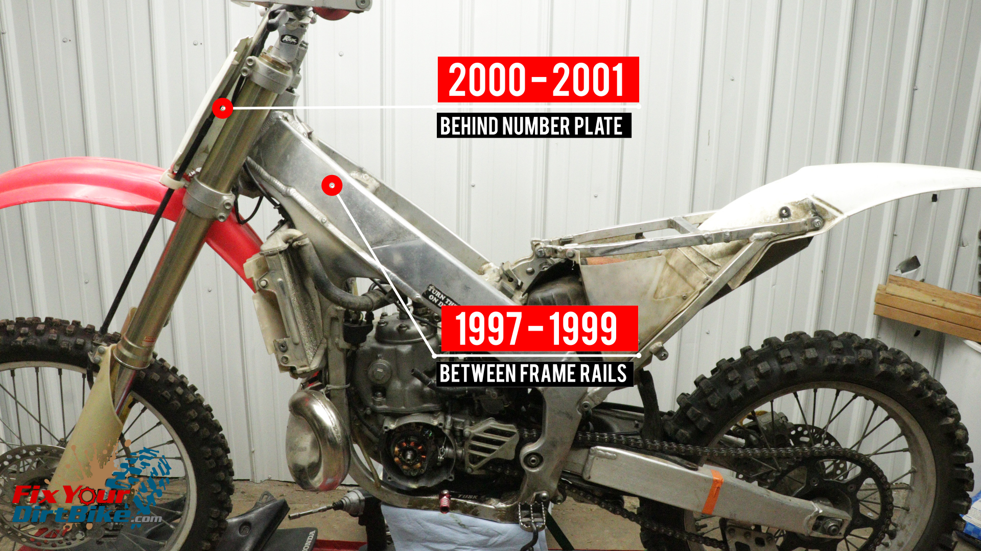
On 1997 – 1999 models, the radiator is one piece, and on 2000 – 2001 models, the radiator is a two-piece design with hoses connecting each side. This service applies to both types of radiators, as well as pretty much every radiator.
How To Service The Radiator On Your 1997-2001 Honda CR250
The radiator is the most fragile component of your dirt bike’s engine, but it’s mounted right behind the fender, so you should inspect it regularly.
On 1997 – 1999 models, the radiator is one piece, and on 2000 – 2001 models, the radiator is a two-piece design with hoses connecting each side. This service applies to both types of radiators, as well as pretty much every radiator.
My radiator looks half-way f****d but still works so…
Before we begin, this is one of those situations where I’m not going to make much effort to fix the part because it’s just not worth it for me. I can get an aftermarket radiator with hoses for around $100, and it will be here in two days.
I’m going to fix the bent tab, test it, then correct the fins. If I find a leak, obstruction or, internal corrosion, I’ll just get a new one, but I’ll still cover how to fix those issues.
Service pictures with captions follow the steps below.
Radiator Components
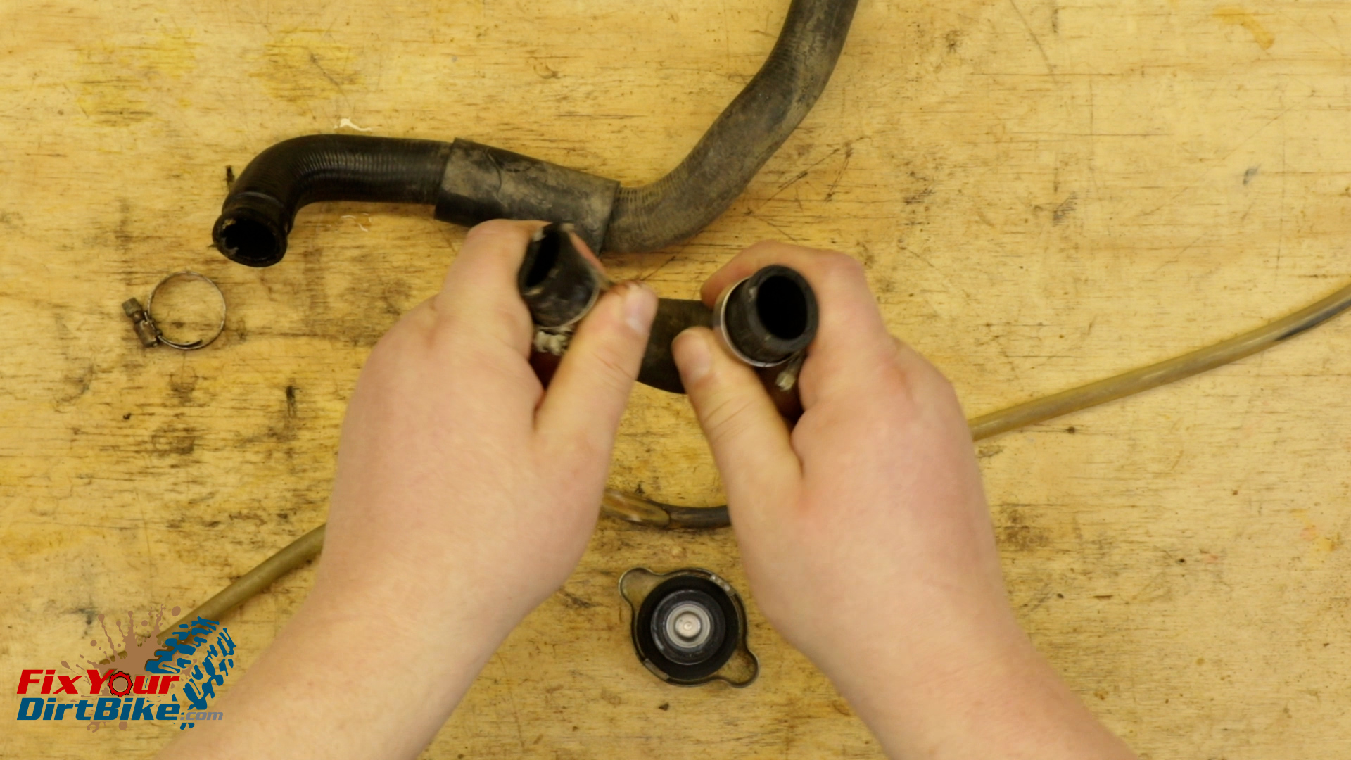
Check your cooling hoses for pliability and general deterioration, if they are stiff, they need to be replaced soon.
Make sure the overflow tube is in good condition, as you can tell, mine got cozy with the exhaust.
Check the cap rubber and spring condition, if the rubber is cracked or the metal has excessive corrosion, replace it.
Check your cooling hoses for pliability and general deterioration, if they are stiff, they need to be replaced soon.Make sure the overflow tube is in good condition, as you can tell, mine got cozy with the exhaust.
Body
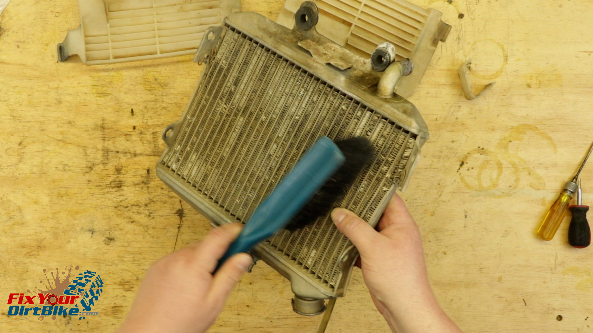
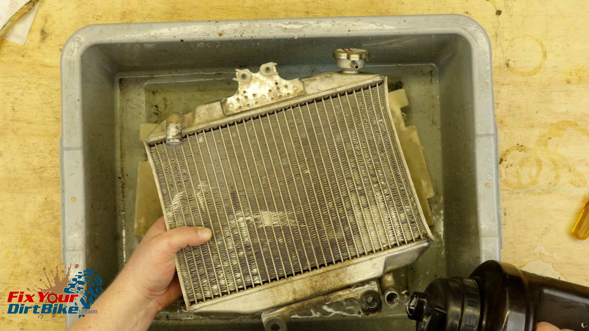
Strip your radiator and give it a good dry brushing with a SOFT brush to avoid damaging the fins.
Do NOT use compressed air to clean the radiator.
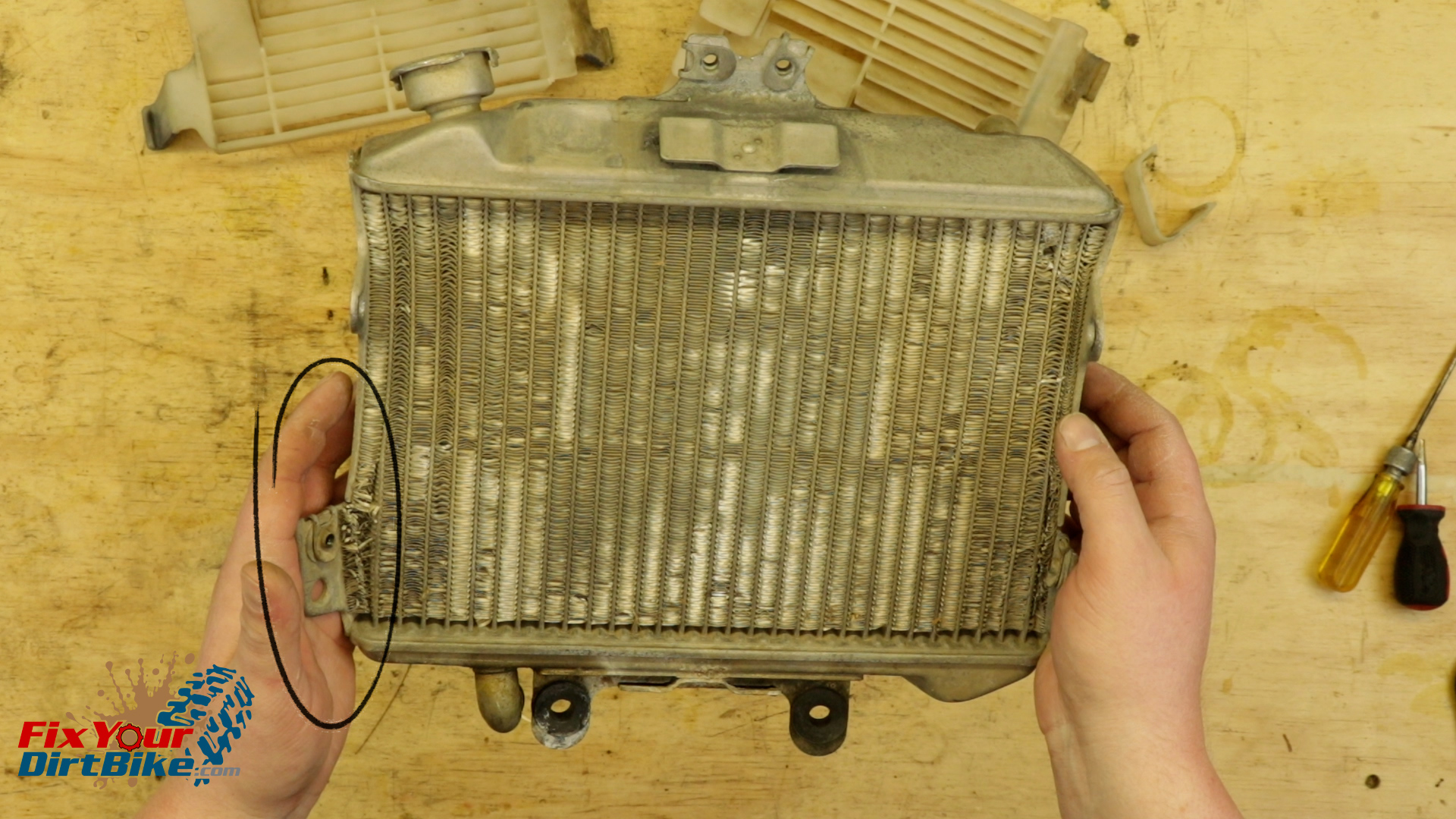
Inspect the radiator body for any obvious damage like cracks, huge dents, or bent mounting tabs.
If you see a greenish residue on the body, there’s probably a leak nearby.
Strip your radiator and give it a good dry brushing with a SOFT brush to avoid damaging the fins.Inspect the radiator body for any obvious damage like cracks, huge dents, or bent mounting tabs.
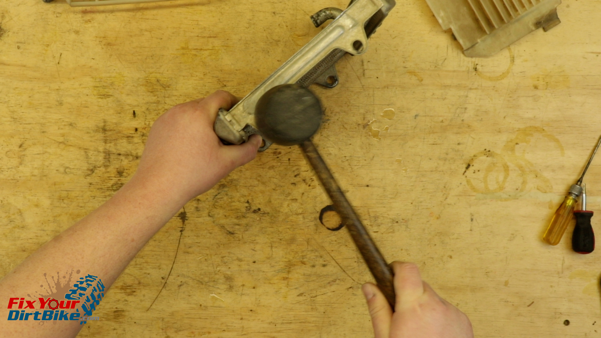
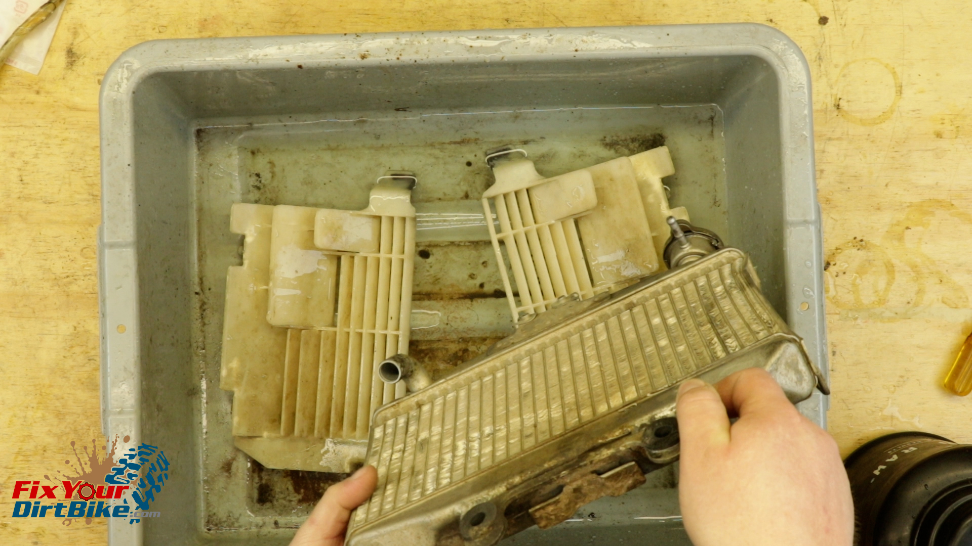
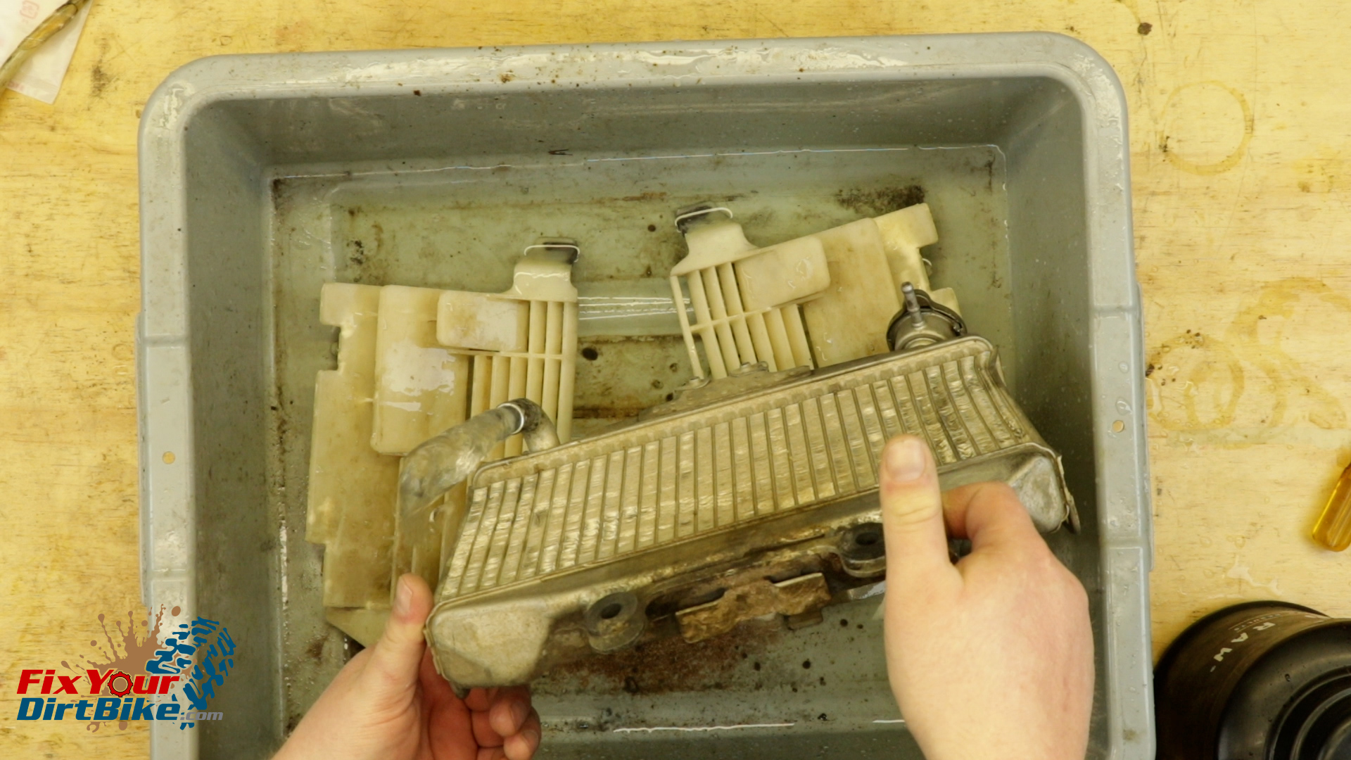
Mine took a hit to the lower right, and the sides have been pushed in. There isn’t much I can do about the sides, but I can bend that mounting tab back into place. After some percussive maintenance, it’s time for testing.
Lemme Smash
Testing
This test will cover three things: big leaks, flow, and corrosion.
Cap the radiator, hold it flat and fill it with water.
Hold the radiator flat for a few minutes and check for leaks. If you find any, mark them with a sharpie.
Plug one end of the radiator with your finger and turn it s,o the open end is lower. If the water holds, your radiator is sealed, if it has a leak, the water will drip or trickle.
Release your finger and watch the flow, if the flow is weak, you have an obstruction.
If your flow is obstructed, you probably have corrosion in the radiator body.
Repeat with the other end.
Cap the radiator, hold it flat and fill it with water.Plug one end of the radiator with your finger and turn it s,o the open end is lower. If the water holds, your radiator is sealed, if it has a leak, the water will drip or trickle.Release your finger and watch the flow, if the flow is weak, you have an obstruction.
The last cooling system test to perform is a pressure test, and the only way to do this accurately is with a specialized testing tool. The only way to perform a pressure test at home is to install your radiator, bring your bike up to operating temp and check for leaks.
If you can locate the source of a leak, you can seal it with a high heat epoxy resin.
If corrosion is evident in the radiator, you will need to reinstall it and run cleaner through the system, then flush with fresh coolant.
If the flow is still obstructed, get a new radiator.
The crack by the mounting tab on my radiator didn’t cause a leak, but I’m going to patch it, so it doesn’t get any bigger.
Radiator Fin Correction
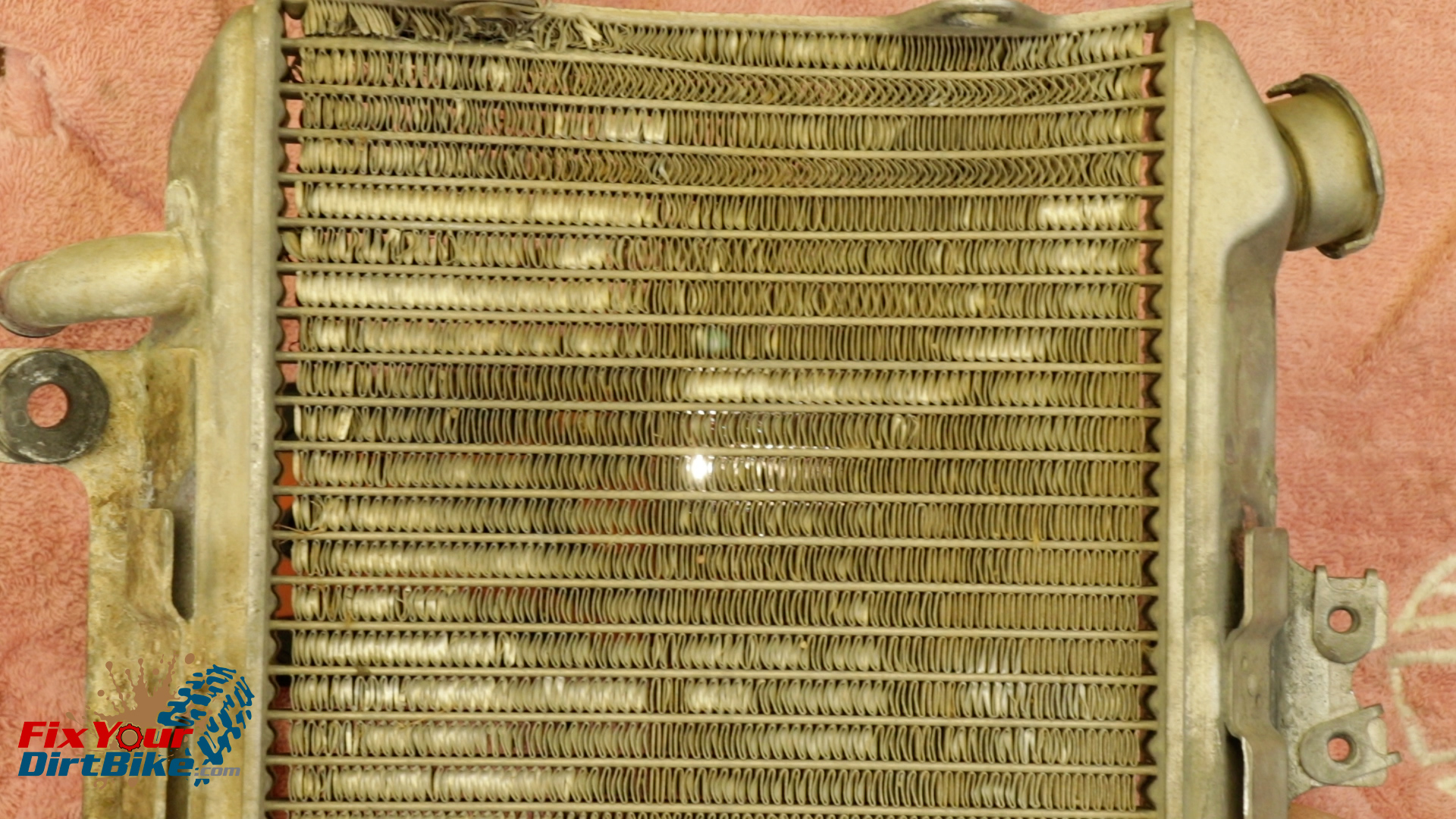
These fins look terrible, but looks can be deceiving.
Hold your radiator up to the light, If you can see through, air can move through.
I’m going to correct a few of the bad spots, but beyond that, it’s not worth it. Plus, the more you correct the fins, the more chance of causing more damage.
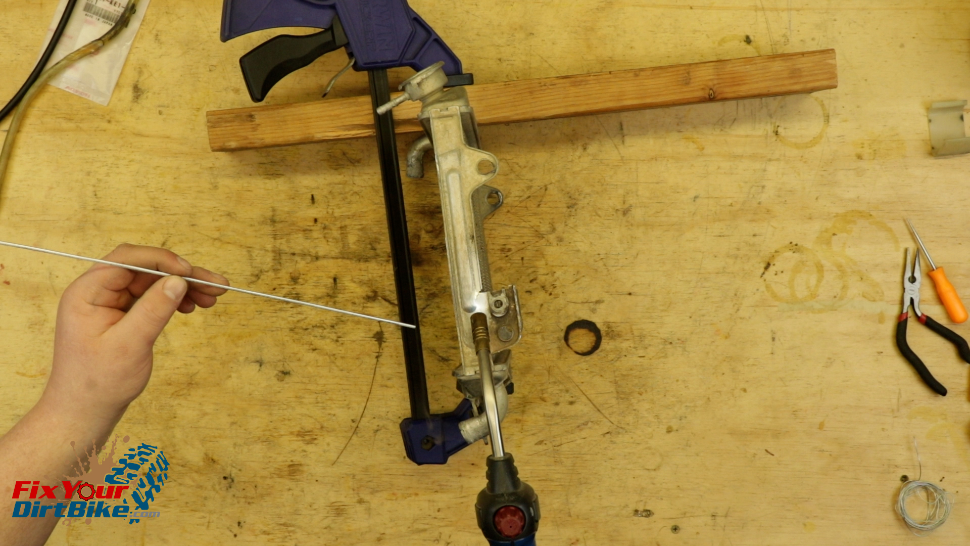
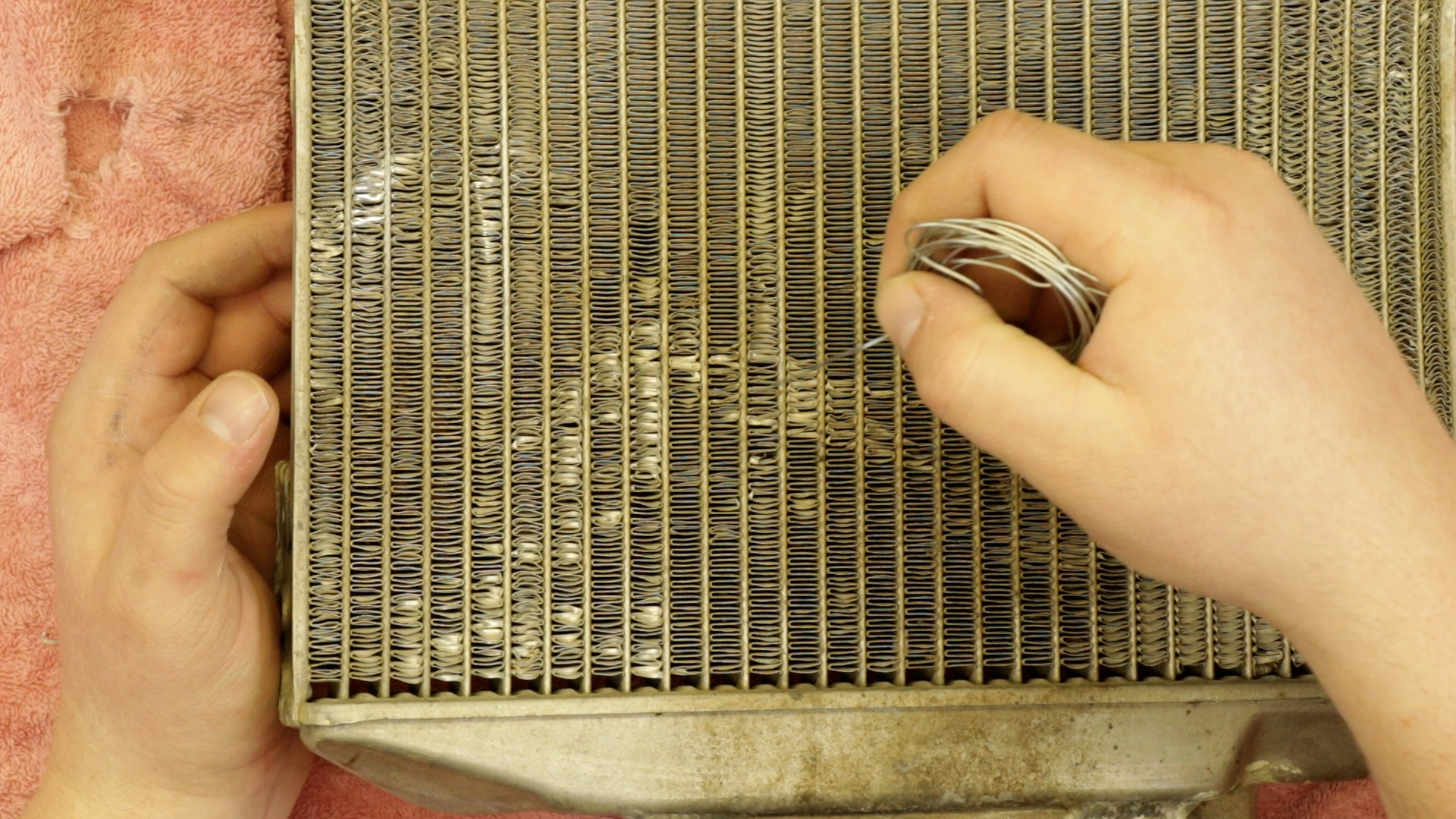
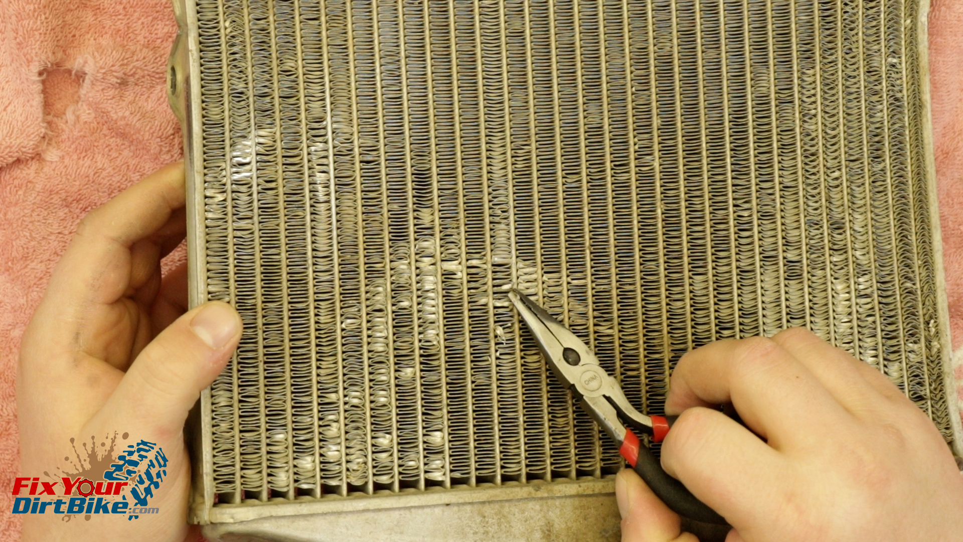
When correcting the fins, push from the other side with a wire instead of trying to pry them out from the front.
As you go, the folded fin will most likely break instead of straightening, but that’s ok because unrestricted airflow with a smaller surface area is better than nothing.
Hold your radiator up to the light, If you can see through, air can move through.When correcting the fins, push from the other side with a wire instead of trying to pry them out from the front.As you go, the folded fin will most likely break instead of straightening, but that’s ok because unrestricted airflow with a smaller surface area is better than nothing.
Is Your Clutch Inner And Outer Binding When Torqued?
If the clutch on your Honda CR250 is binding when you torque the center bolt, pull the outer and check how far the kickstarter gear is sticking out from the back of the basket.
I want to give a huge shoutout to Brian from Georgia for figuring out a problem I didn’t even know existed!
Brian was experiencing this binding issue, so I asked him to send me a message on Facebook so we could troubleshoot with pictures and video, and we found the thrust washer was worn out, problem solved, right?
A few hours later, Brian sent me a link to a forum post on Oem-Cycle.com with the possible cause beyond a warped washer, and it was something I had never experienced.
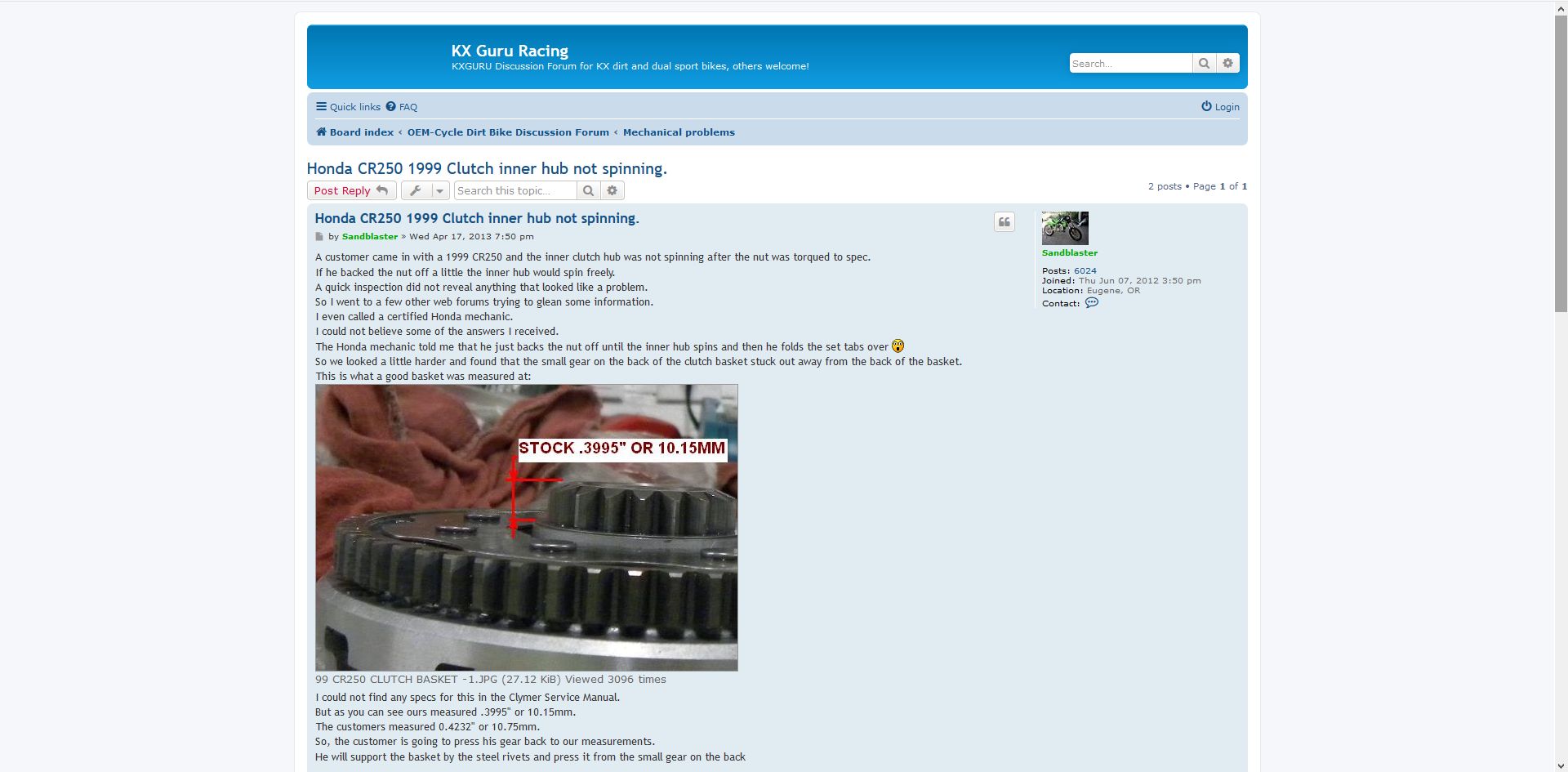
The user on the forum goes by Sandblaster, and they found out that the kickstarter gear would work its way out of the clutch basket, forcing the basket forward just enough to bind.
And by “just enough,” I mean less than a millimeter.
There are no specs for the correct height in the Clymer manual, so Sandblaster used a different clutch off a 1999 CR250 as a reference that measured at 10.15mm.
Brian’s clutch basket measured at 10.38mm, he pressed it back to 9.8mm, and now it spins freely.
This would also explain why some older bikes are hard to push or start when in gear and the clutch pulled, even with a fresh clutch and cable.
I pulled my clutch basket to check, and I measured right at 10.15mm, so that does seem like the OEM spec.
If the clutch on your Honda CR250 is binding when you torque the center bolt, pull the outer and check how far the kickstarter gear is sticking out from the back of the basket.
I want to give a huge shoutout to Brian from Georgia for figuring out a problem I didn’t even know existed!
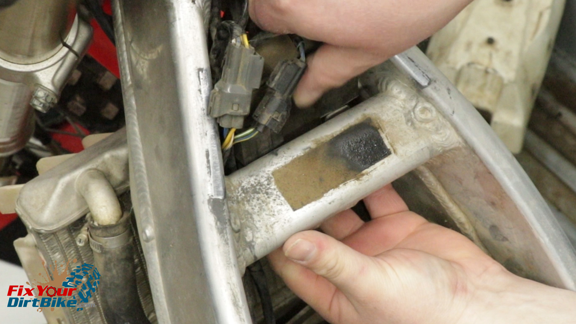
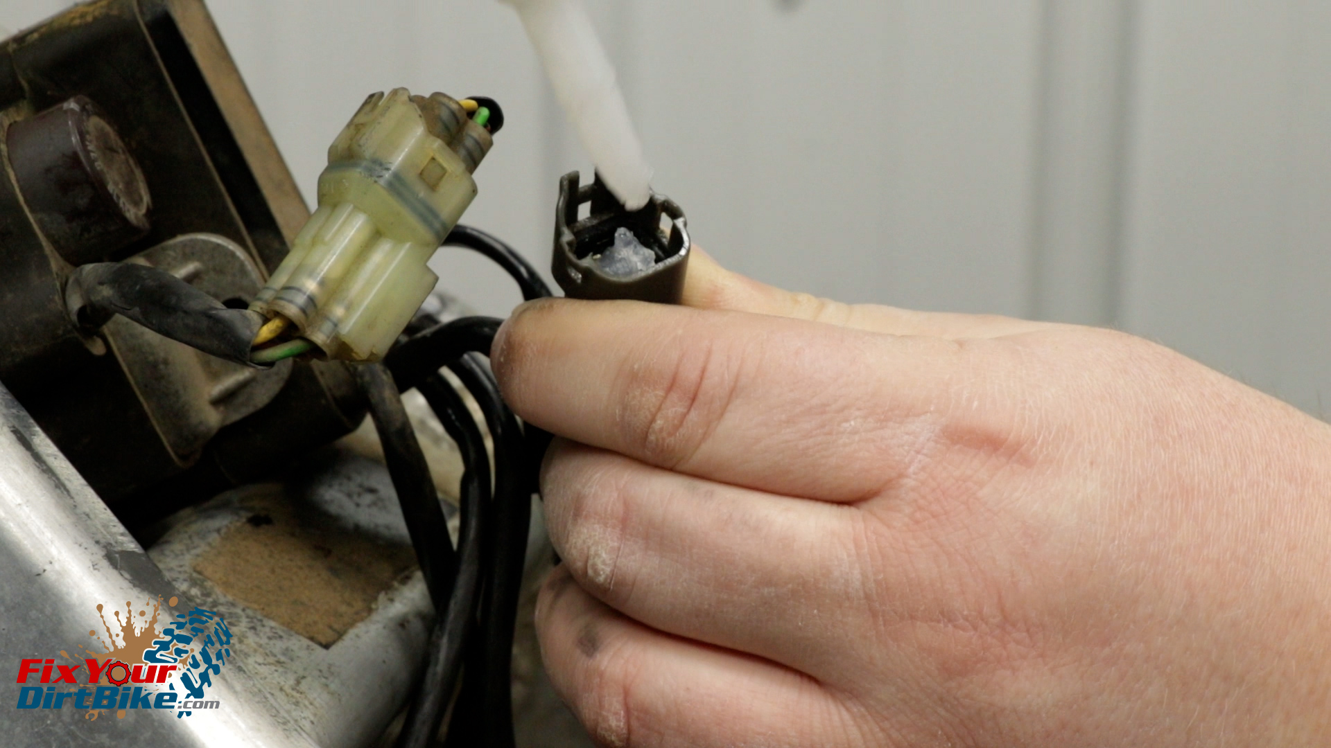
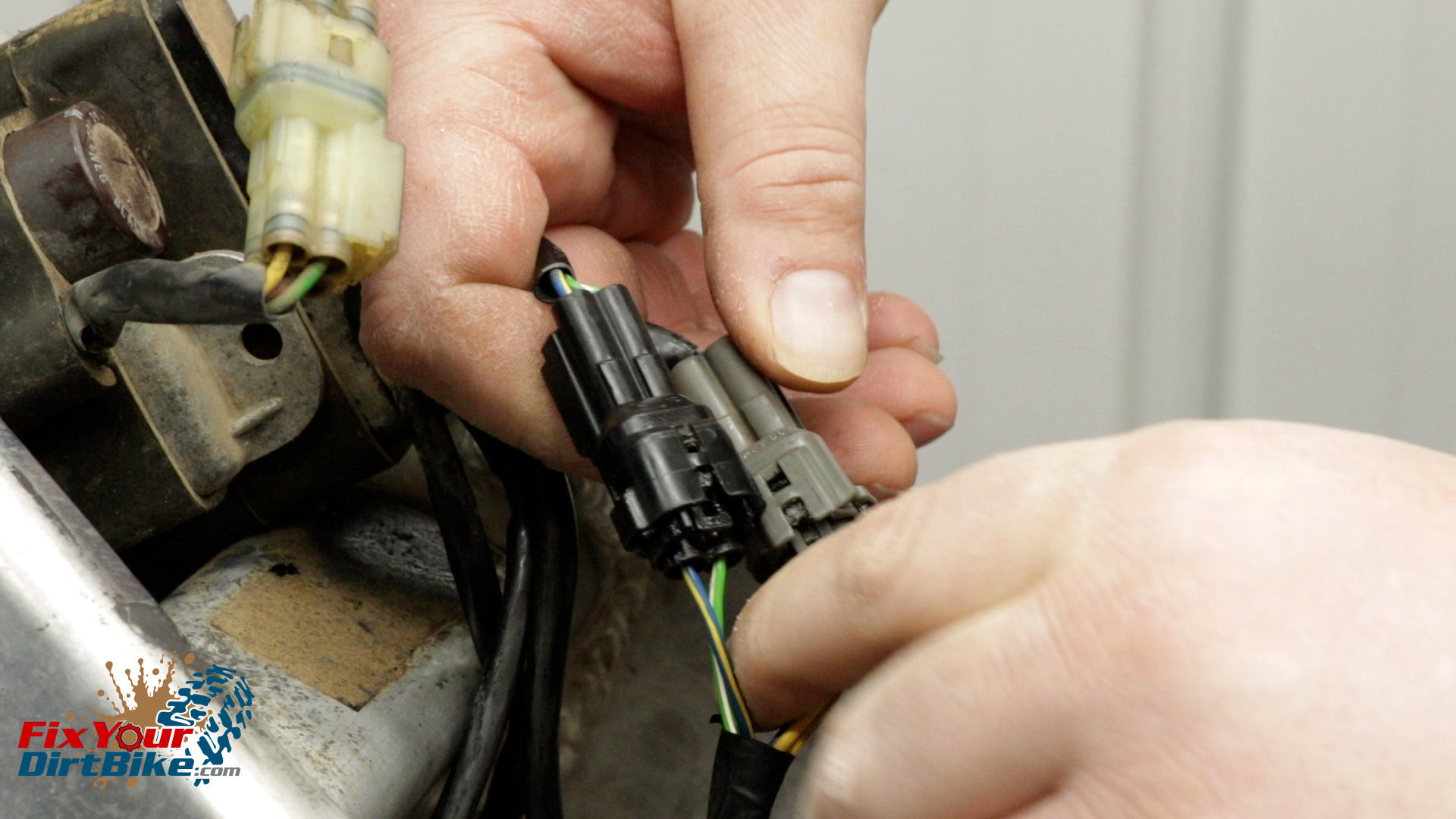
Start by disconnecting the two wiring harnesses from the ignition control module. One will have blue and white wires, and the other will have blue/yellow and green/white wires.
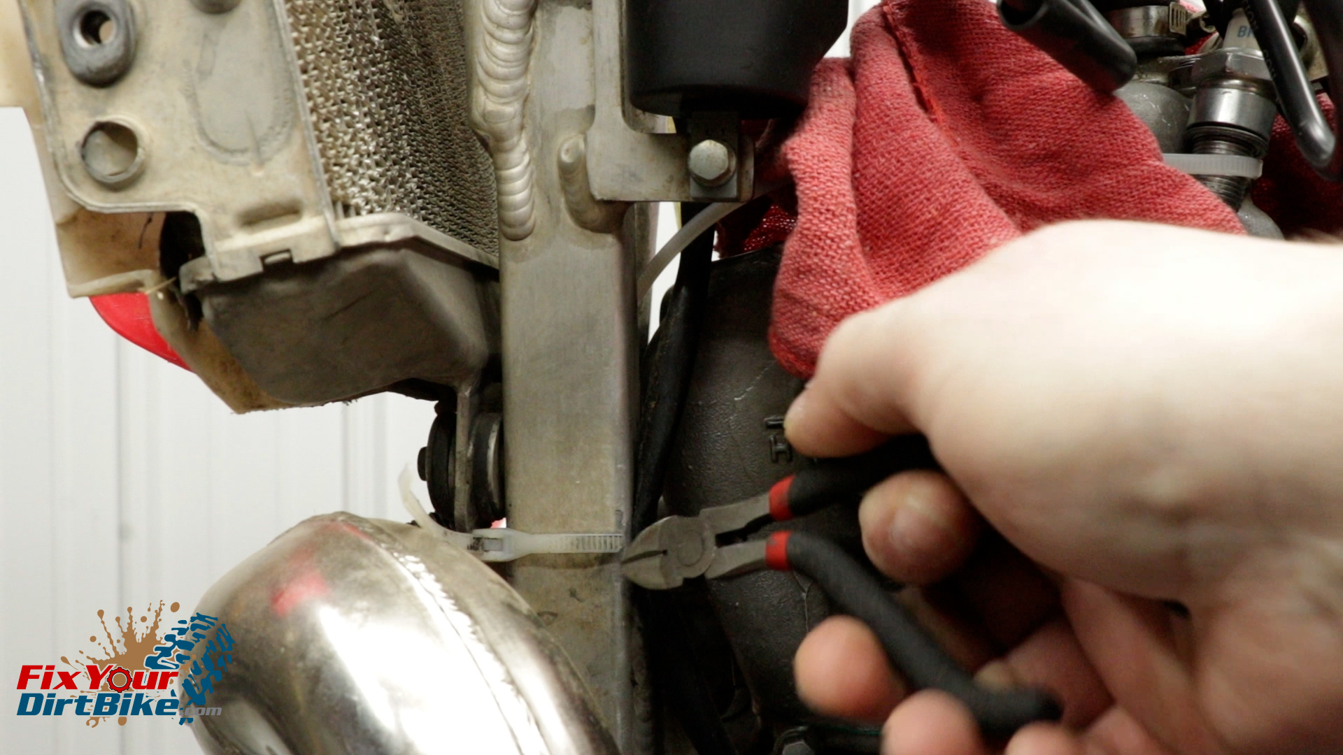
Feed the wiring harnesses down and away from the frame. You may need to cut a few zip ties along the way.
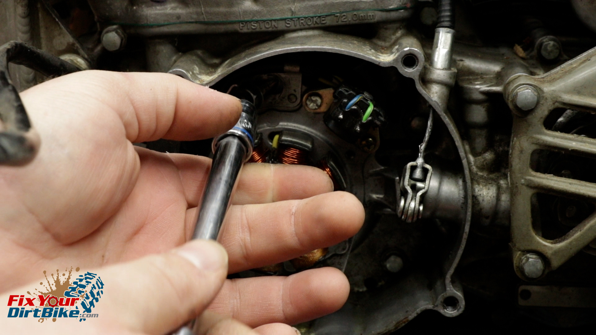
Pull the wiring grommet away from the case, but do not remove it.
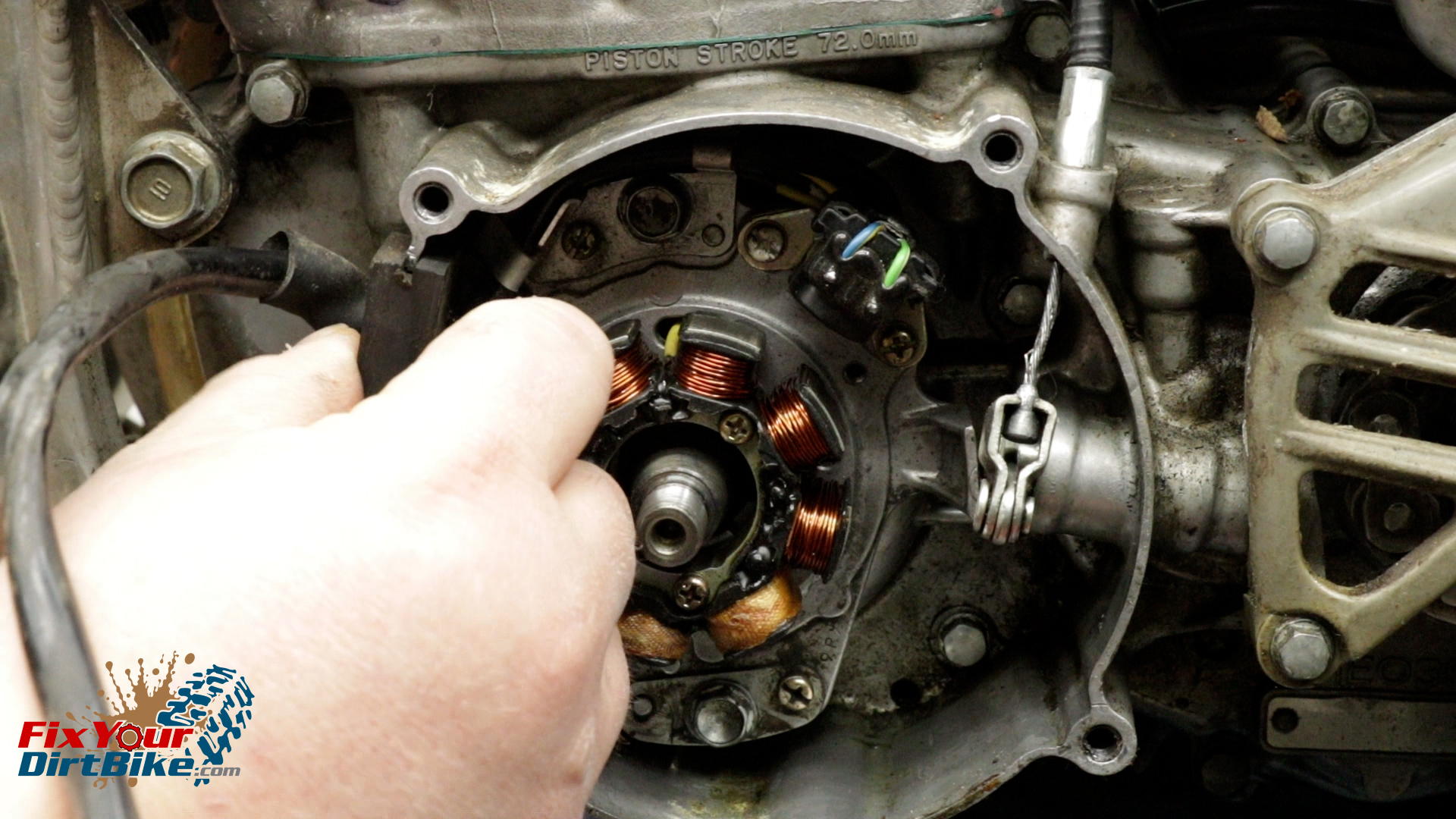
Remove the two mounting bolts from the top and bottom of the stator frame.
Pull the stator and grommet from the case at the same time.
Start by disconnecting the two wiring harnesses from the ignition control module. One will have blue and white wires, and the other will have blue/yellow and green/white wires.Feed the wiring harnesses down and away from the frame. You may need to cut a few zip ties along the way.Pull the wiring grommet away from the case, but do not remove it.Remove the two mounting bolts from the top and bottom of the stator frame.
Stator Installation
Install your stator in the reverse order.
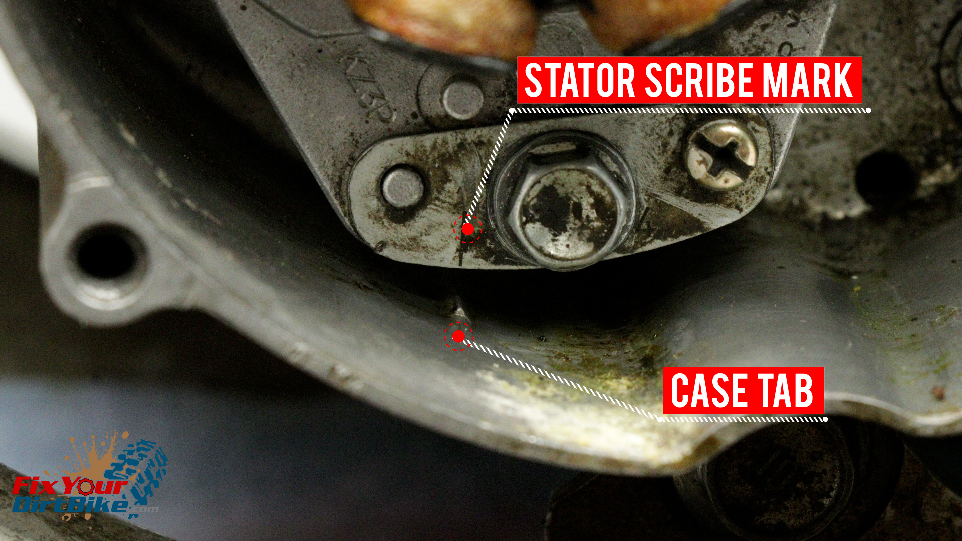
When installing the stator frame, line up the scribe mark on the frame with the tab in the case.
This is the stock timing setting.
Add some dielectric grease to the harnesses before reconnecting.
Connect the stator wires to the ignition control module.
Secure the stator wires to the backside of the frame rails.
When installing the stator frame, line up the scribe mark on the frame with the tab in the case.Add some dielectric grease to the harnesses before reconnecting.Connect the stator wires to the ignition control module.
How To Troubleshoot The Electrical System On Your 1997 – 2001 Honda CR250
If you have no spark or spark with low performance, this is how to troubleshoot the ignition system on your 1997 through 2001 Honda CR250.
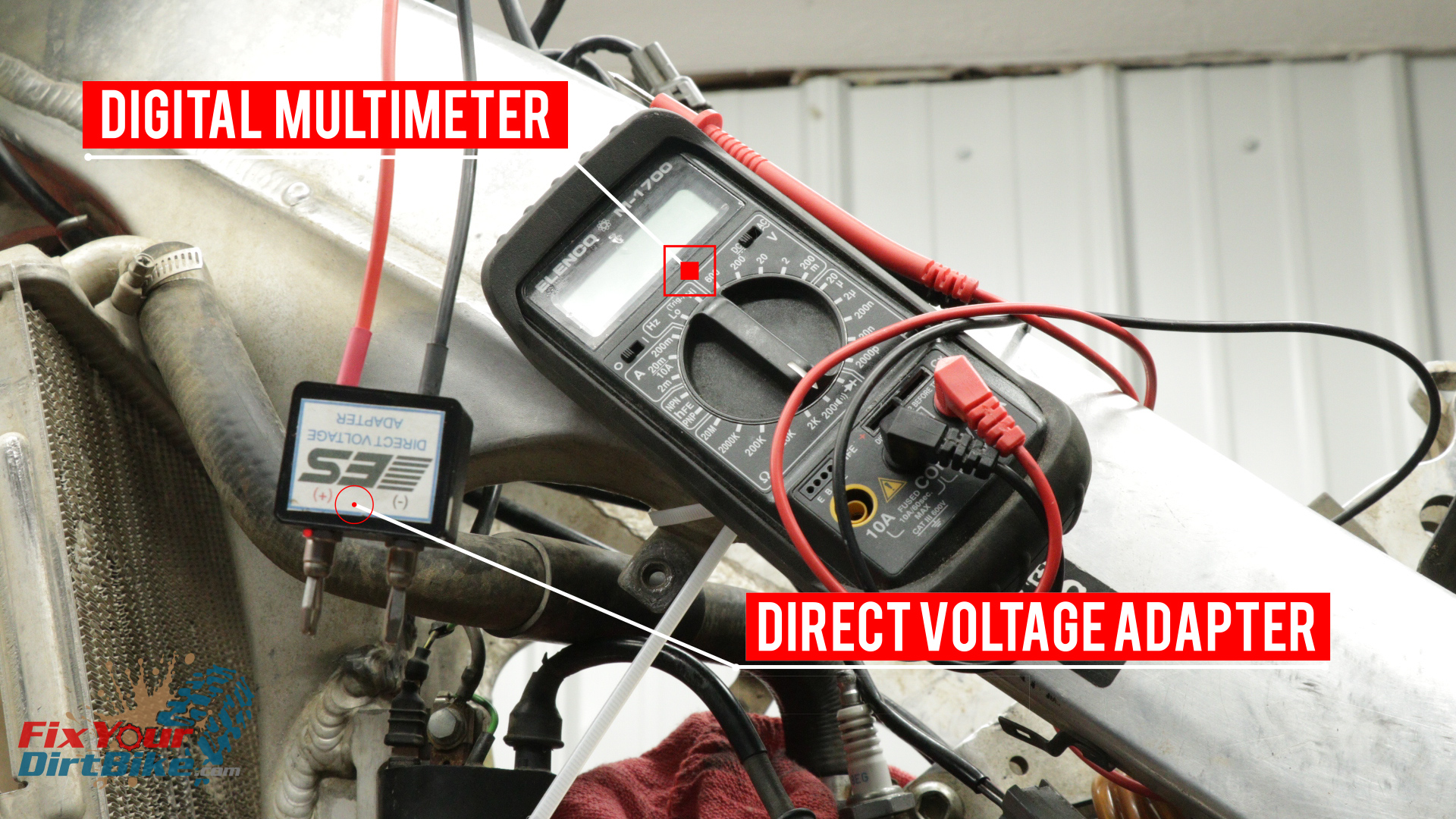
Troubleshooting Parts And Tools:
To test your ignition, you will need a Digital Multimeter and a Direct Voltage Adapter. You can pick up both for around $60 through our retail partners.
How To Troubleshoot The Electrical System On Your 1997 – 2001 Honda CR250
I wanted to use my CR250 as an example of a fully functioning ignition system. As it turns out, sometime in the past month, my ignition coil died, so that’s good, timing?
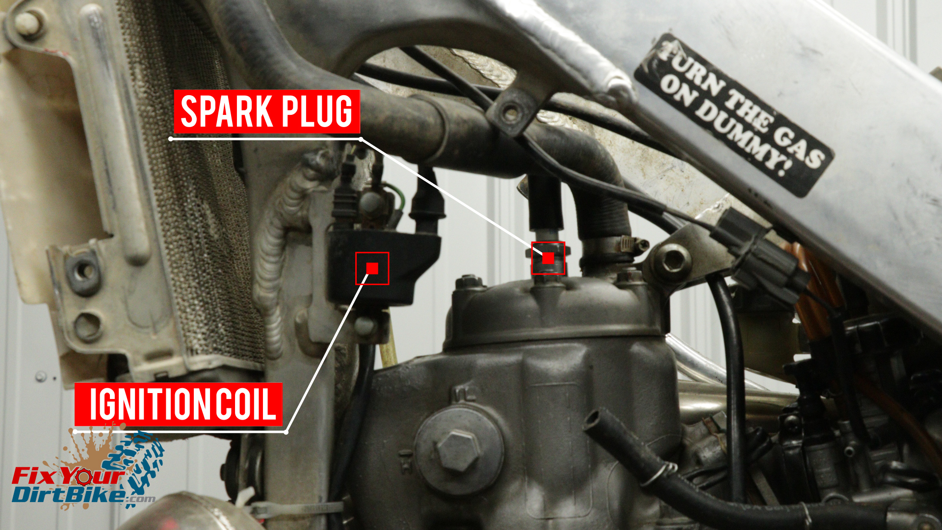
The quickest way to see if you are having ignition system issues is to remove your spark plug, ground it to the outside of the cylinder, turn the lights off, and kick your bike over.
If you have no spark or spark with low performance, this is how to troubleshoot the ignition system on your 1997 through 2001 Honda CR250.
Troubleshooting Parts And Tools:
To test your ignition, you will need a Digital Multimeter and a Direct Voltage Adapter. You can pick up both for around $60 through our retail partners.
Philips Head Screwdriver
Tiny Flat Head Screwdriver
8mm Socket & Wrench
Zip Ties
Handy Wire
Towel
Multimeter
Direct Voltage Adapter (AKA Peak voltage Adapter)
Effective Troubleshooting
Troubleshooting your ignition system only works when you stay organized, write everything down, and take your time, as this can get frustrating very quickly.
To make troubleshooting as easy as possible, do not try to chase the problem. Test each component individually, and write down each test result as you go. Recording each result will let you find the problem on paper instead of jumping around between components.
When troubleshooting each component, you need to test each possible cause In ORDER.
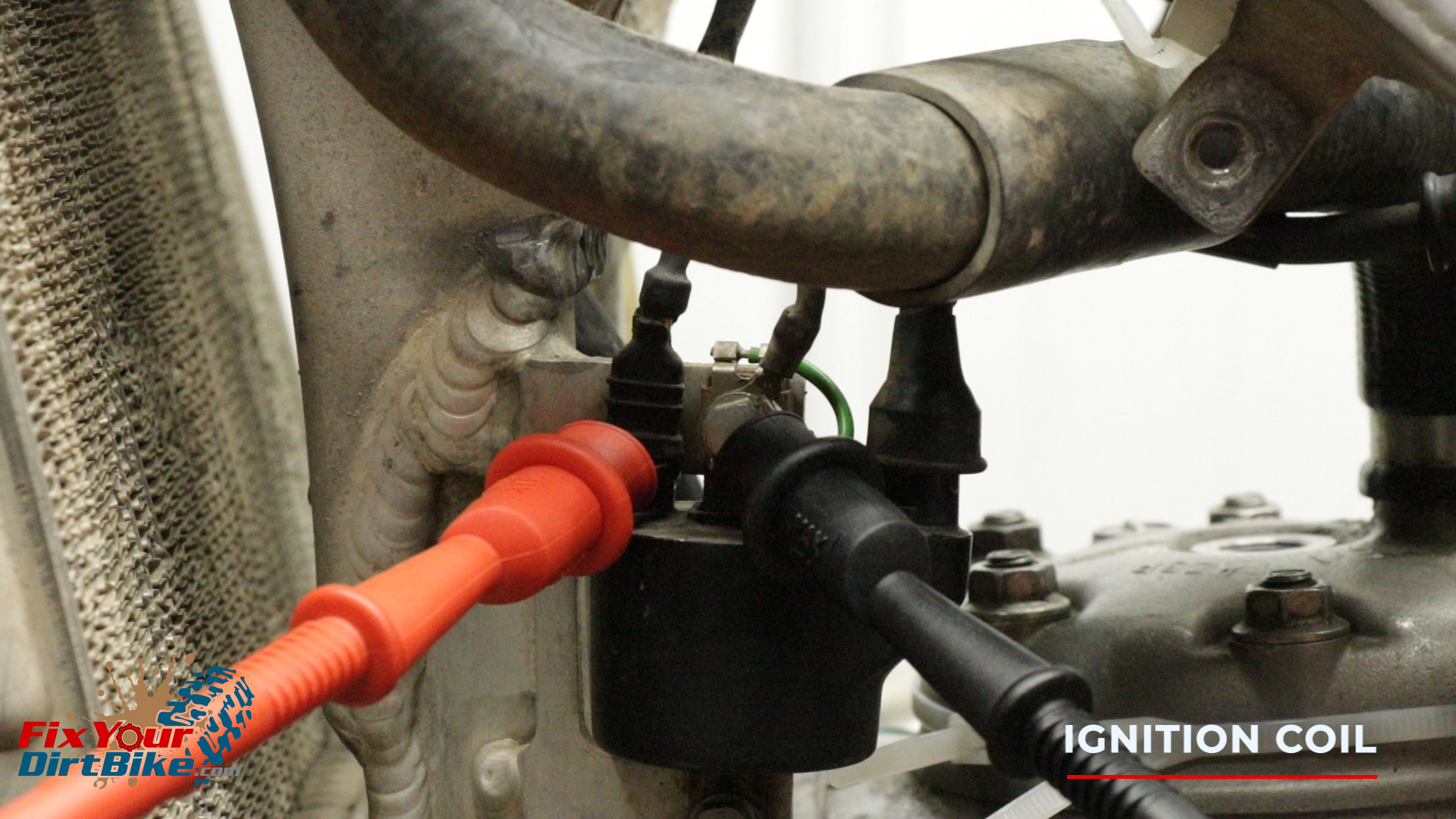
The ignition coil is mounted on the front left of the frame.
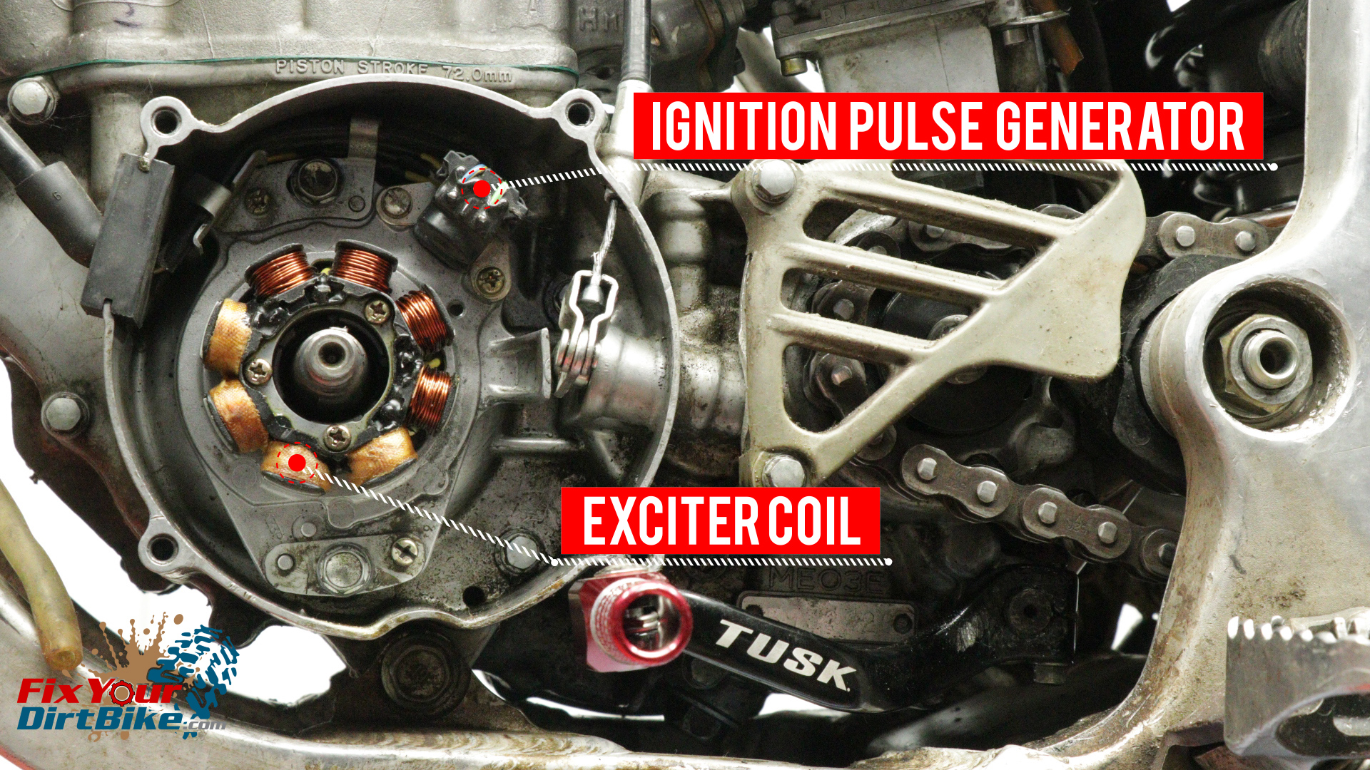
The exciter coil and ignition pulse generator are part of the stator, mounted behind the flywheel.
The ignition control module is mounted between the frame rails under the gas tank on 1997 – 1999 models, and behind the number plate on 2000 – 2001 models.
The ignition coil is mounted on the front left of the frame.The exciter coil and ignition pulse generator are part of the stator, mounted behind the flywheel.The ignition control module is mounted between the frame rails under the gas tank on 1997 – 1999 models, and behind the number plate on 2000 – 2001 models.
Troubleshooting Prep
Start by removing the flywheel cover and gas tank.
You will be testing the stator through the wiring harness, so you DO NOT need to remove the flywheel or the stator.
Remove the Ignition control module by pushing the rubber mount up off the mounting tabs, then down and out toward the back of the bike.
When testing peak voltage, you will need to be able to kick your bike over while keeping the test leads connected.
If you don’t have a helper, strap your bike to something solid, zip tie your multimeter to your bike, and use handy wire in the gator clips of your direct voltage adapter as needed.
Remove your spark plug and ground it to the cylinder.
It is critical that you keep your spark plug grounded throughout testing! An ungrounded plug can destroy the ignition coil!
Make sure you have a fresh spark plug and cover the spark plug hole with a towel.
Remove the Ignition control module by pushing the rubber mount up off the mounting tabs, then down and out toward the back of the bike.
Ignition Control Module
The ignition control module is also known as a CDI. The Ignition control module cannot be tested and is not serviceable. The only way to test it is by testing everything else. If every other component passes, then you know the Ignition control module has gone bad.
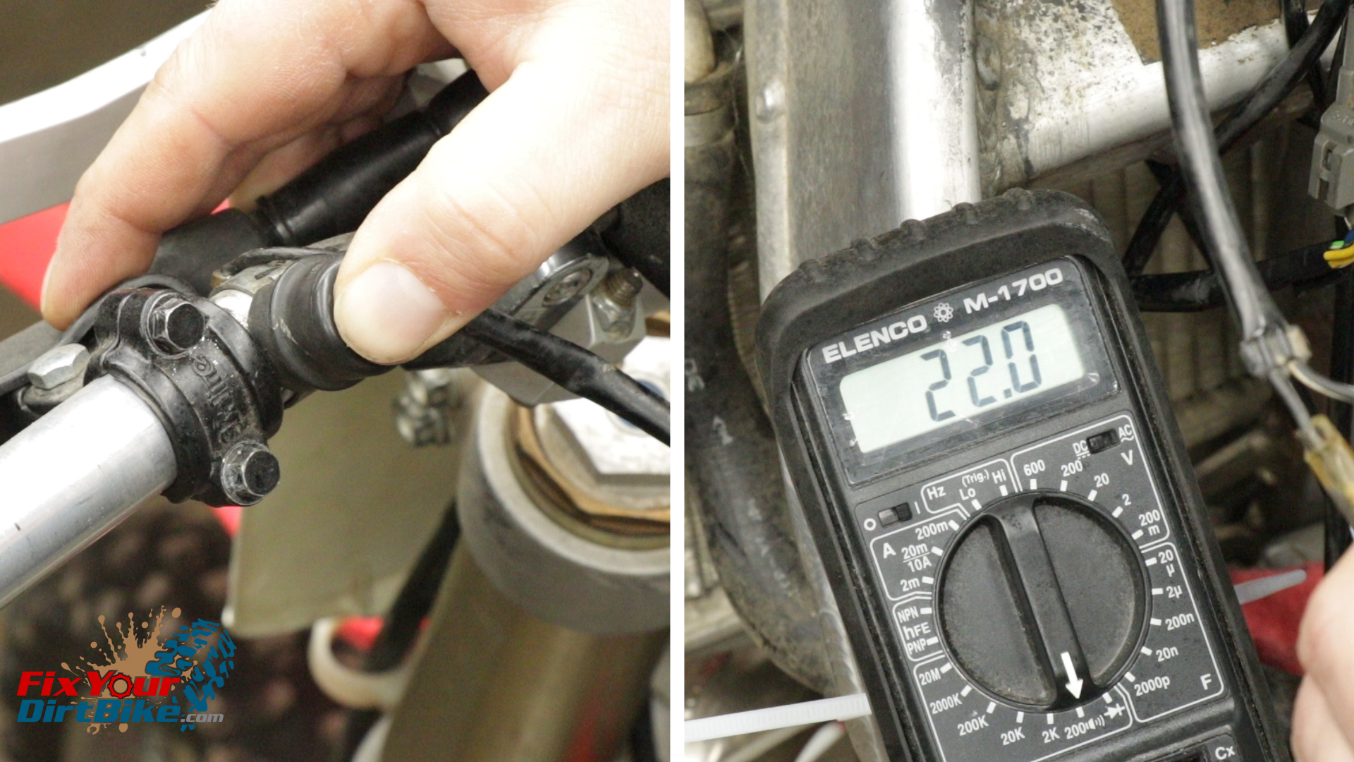
Engine Stop Switch
If you have No spark, test your engine stop switch first, because that’s usually the problem.
Set your multimeter to the lowest Ohm setting, and connect the leads to the tails.
While holding the leads to the tails, push the stop switch.
With the button pushed, you should see continuity at the meter. If you read continuity without pressing the button, the stop switch is bad.
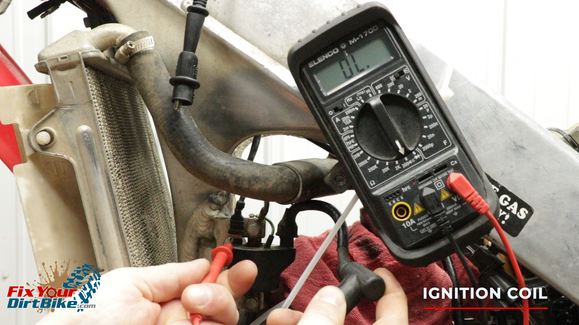
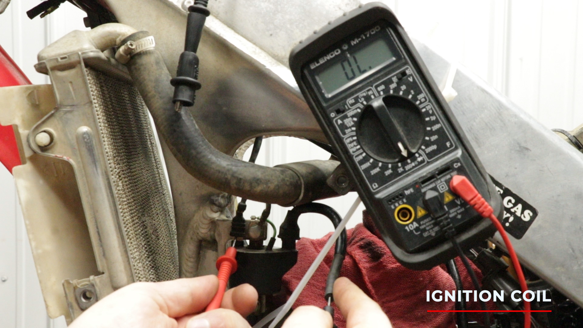
Ignition Coil Testing
Test The ignition coil for peak voltage, along with resistance between three points.
Primary to Ground
Primary to Plug Boot
Primary to Plug Wire
Ignition Coil Peak Voltage Test
To test peak voltage, connect your positive test lead to the black/yellow primary terminal, and the negative test lead to the ground bolt.
Set your multimeter to 200 volts, DC.
Kick your bike over as fast as possible to get an accurate reading.
Your ignition coil peak voltage should be at least 100 volts.
To test peak voltage, connect your positive test lead to the black/yellow primary terminal, and the negative test lead to the ground bolt.
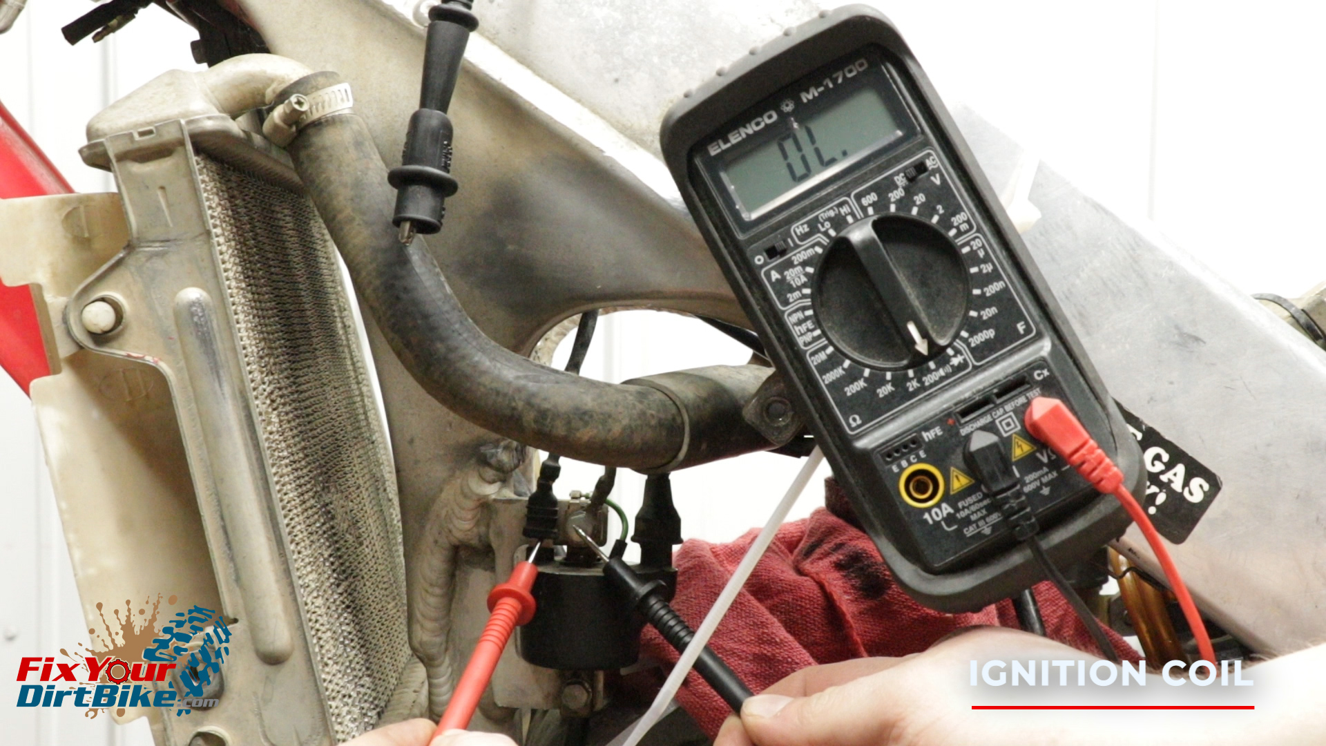
Ignition Coil Resistance Test
To test the primary coil resistance, remove your direct voltage adapter from your multimeter, and connect the standard test leads.
Set your multimeter to 200 Ohms
Touch the positive test lead to the primary terminal, and the negative test lead to the ground bolt.
Your primary ignition coil should be between 0.2-0.4 Ohms on 1997-1999 models and 0.1-0.3 Ohms on 2000-2001 models.
To test the secondary coil, keep the positive test lead on the primary terminal, and touch the negative test lead to connection inside the spark plug boot.
Your secondary coil should be between 9 and 16 ohms with the spark plug boot connected.
Remove the spark plug boot, and insert the negative test lead into the end of the plug wire.
Your secondary coil should be between 4 and 8 ohms without the spark plug boot.
Touch the positive test lead to the primary terminal, and the negative test lead to the ground bolt.To test the secondary coil, keep the positive test lead on the primary terminal, and touch the negative test lead to connection inside the spark plug boot.Remove the spark plug boot, and insert the negative test lead into the end of the plug wire.
Ignition Coil Troubleshooting
If Your Ignition Coil Shows A Low Peak Voltage, Check The Following In Order:
Bad Direct Voltage Adapter Connections
Meter Impedance Is Too Low
Cranking Speed Is Too Low
Test And Pulse Not Synchronized (If Measured Voltage Is Over Minimum Once The System Is Normal)
Poor Connection Or Open Circuit
Bad Exciter Coil
Bad Ignition Coil
Bad Ignition Control Module (When All Others Check Out)
If Your Ignition Coil Shows No Peak Voltage, Check The Following In Order:
Bad Direct Voltage Adapter Connections
Short In Engine Stop Switch
Bad Engine Stop Switch
Poor Ignition Control Module Connection
Open Circuit Or No Ground Of Ignition Control Module
Bad Direct Voltage Adapter
Bad Exciter Coil
Bad Ignition Pulse Generator
Bad Ignition Control Module
If You Are Reading Correct Voltage With No Spark:
Bad Spark Plug
Leaking Ignition Coil Secondary Current
Bad Ignition Coil
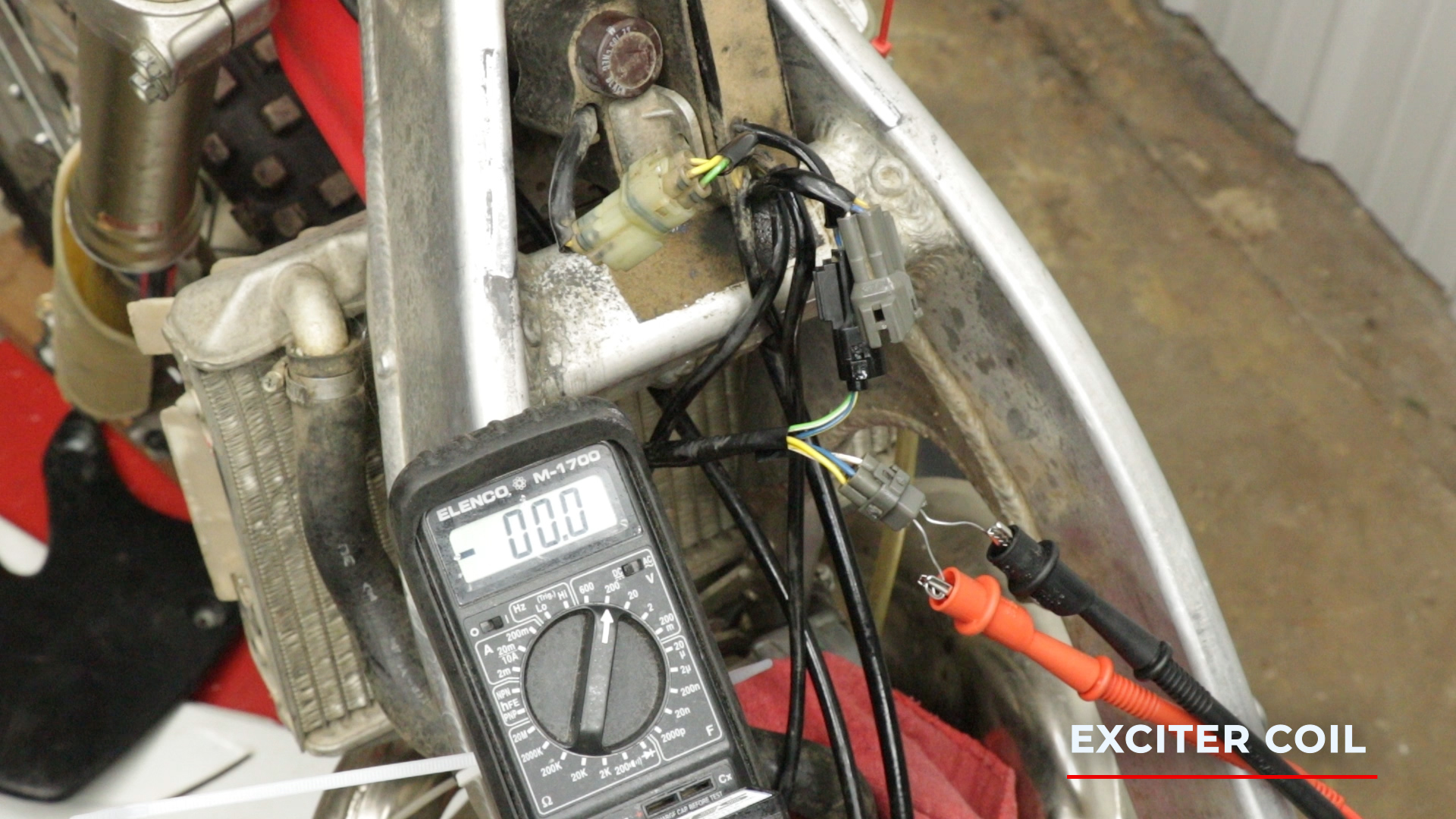
Exciter Coil Testing
Exciter Coil Peak Voltage Test
The exciter coil is part of the stator, but you will test it at the ignition control module.
Disconnect the wiring harness with the blue and white wires.
To test the exciter coil peak voltage, connect your direct voltage adapter to your multimer, and set it to 200 volts DC.
Connect the positive test lead to the blue wire terminal, and the negative test lead to the white wire terminal.
Be sure to connect the leads under the connections, and the wire extensions should reach about ¼ inch into the harness.
Kick your bike over and record the peak voltage.
The exciter coil peak voltage should be at least 100 volts.
Connect the positive test lead to the blue wire terminal, and the negative test lead to the white wire terminal.
Side Note:
Unfortunately, it’s tough to get a reliable reading on the exciter coil peak voltage, because you will not be able to kick your bike over fast enough. When starting your bike, you really only have to kick once or twice, and then inertia takes over, and the bike does the rest.
As you can see here, I am kicking the absolute shit out of my bike and barely reading over 20 volts. So consider this when doing your on-paper troubleshooting, and come back to it if needed.
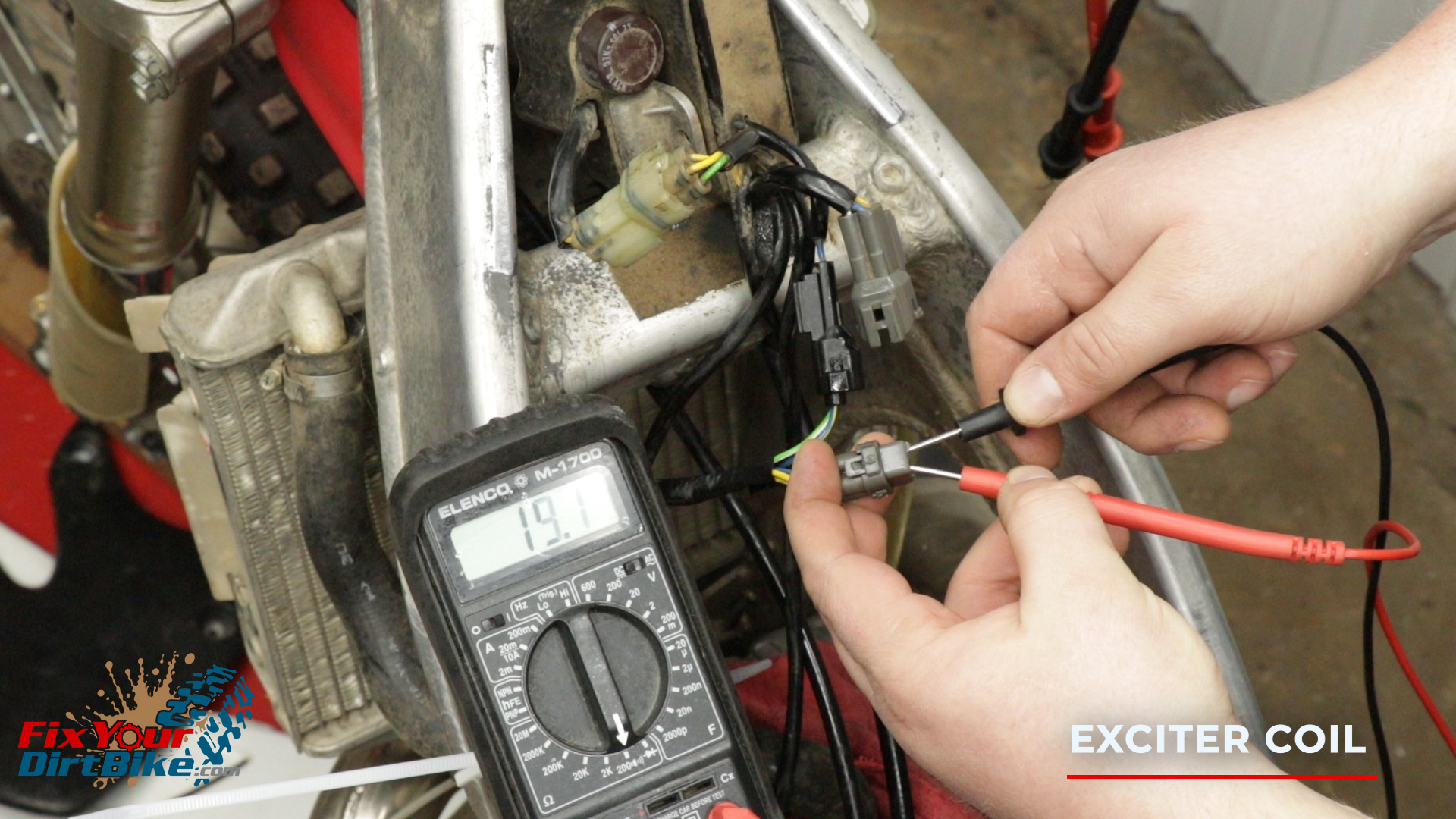
Exciter Coil Resistance Test
To test the resistance of the exciter coil, use the standard test leads, and set your multimeter to 200 Ohms.
Connect the positive test lead to the blue wire terminal, and the negative test lead to the white wire terminal.
The resistance should be between 2-20 Ohms on 1997 through 1998 models and between 9-25 Ohms on 1999 through 2001 models.
Apply dielectric grease to the inside of the wiring harness and reconnect the exciter coil.
Connect the positive test lead to the blue wire terminal, and the negative test lead to the white wire terminal.
Exciter Coil Troubleshooting
If Your Exciter Coil Shows A Low Peak Voltage, Check The Following In Order:
Meter Impedance Is Too Low
Cranking Speed Is Too Low
Test And Pulse Not Synchronized (If Measured Voltage Is Over Minimum Once The System Is Normal)
Bad Ignition Control Module
If Your Exciter Coil Shows No Peak Voltage, Check The Following In Order:
Bad Direct Voltage Adapter
Bad Exciter Coil
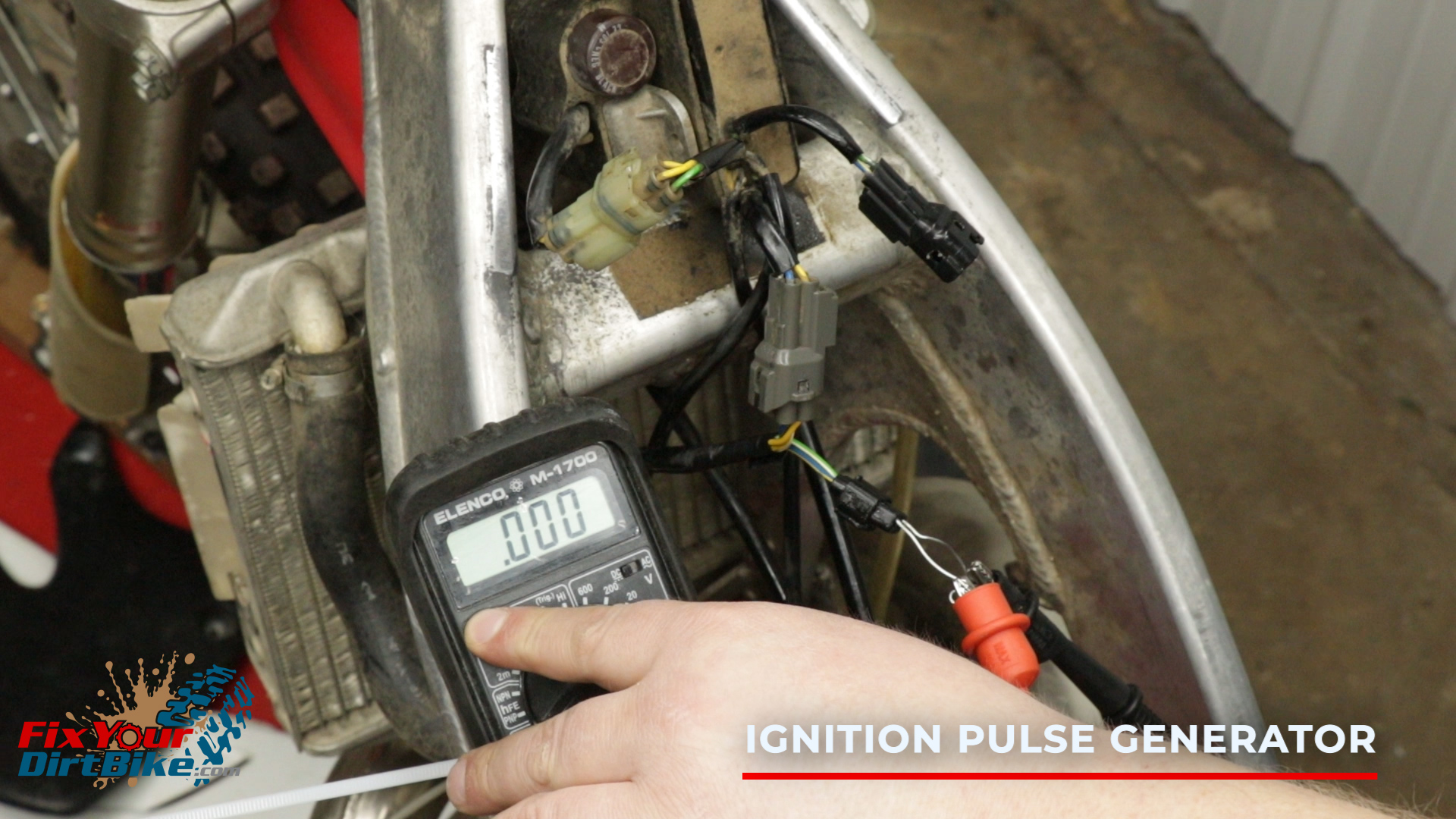
Ignition Pulse Generator
The ignition pulse generator is part of the stator but you will test it at the Ignition control module. Disconnect the wiring harness with the blue/yellow and green/white wires.
Ignition Pulse Generator Peak Voltage Test
To test the ignition pulse generator peak voltage, connect your direct voltage adapter to your multimer, and set it to 2 volts DC.
Connect the positive test lead to the blue/yellow wire terminal, and the negative test lead to the green/white wire terminal.
Kick your bike over and record the peak voltage.
The ignition pulse generator peak voltage should be at least 0.7 volts.
Connect the positive test lead to the blue/yellow wire terminal, and the negative test lead to the green/white wire terminal.
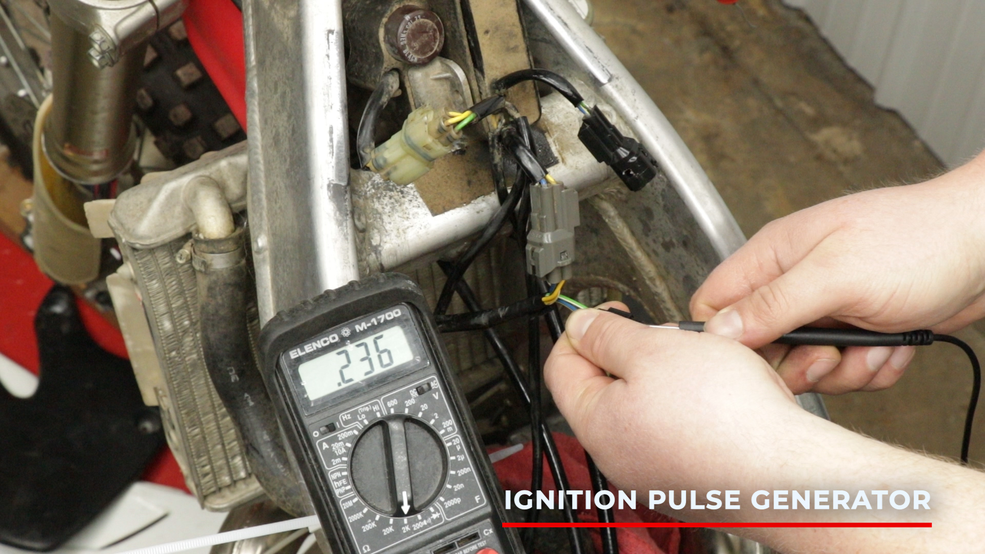
Ignition Pulse Generator Resistance Test
To test the resistance of the ignition pulse generator, use the standard test leads, and set your multimeter to 2,000 (2K) Ohms.
Connect the positive test lead to the blue/yellow terminal, and the negative test lead to the green/white terminal.
The resistance should be between 180 and 280 ohms.
Apply dielectric grease to the inside of the wiring harness and reconnect the ignition pulse generator.
Connect the positive test lead to the blue/yellow terminal, and the negative test lead to the green/white terminal.
Ignition Pulse Generator Troubleshooting
If Your Ignition Pulse Generator Shows A Low Peak Voltage, Check The Following In Order:
Meter Impedance Is Too Low
Cranking Speed Is Too Low
Test And Pulse Not Synchronized (If Measured Voltage Is Over Minimum Once The System Is Normal)
Bad Ignition Control Module
If Your Ignition Pulse Generator Shows No Peak Voltage, Check The Following In Order:
Bad Direct Voltage Adapter
Bad Ignition Pulse Generator
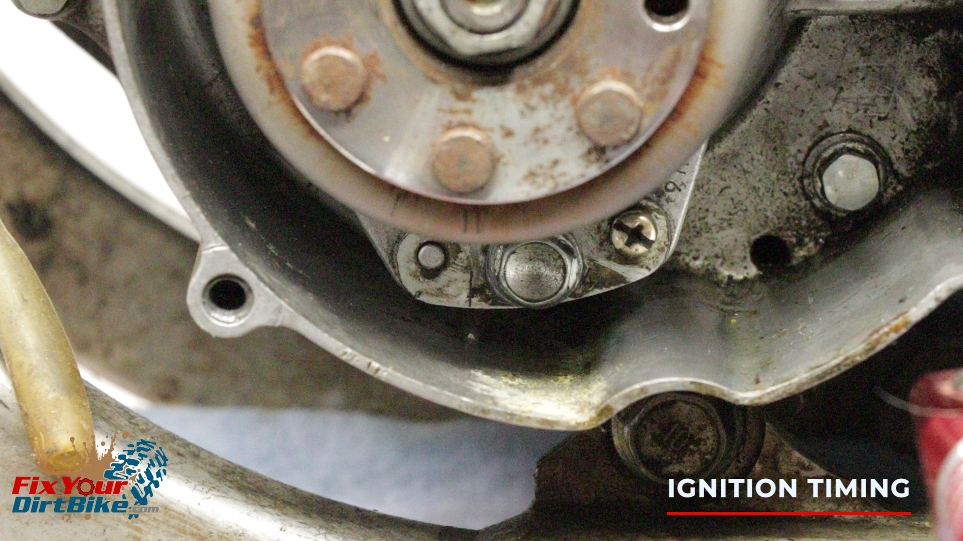
Ignition Timing
To fully read and adjust the timing, you will need a timing gun and a tachometer. Or, you can make sure the tab on the crankcase and the mark on the stator are aligned and call it a day.
If you have an aftermarket flywheel, make sure the magnet lines up with the ignition pulse generator, and the double scribe marks line up to the stator. While not impossible, it is highly improbable that the timing would be off if your CR is stock.
Power Jet Solenoid
I did not cover the power jet solenoid for two reasons:
It only came on 97 and 98 models
It never really worked when it did work
If you really want to test your power jet solenoid message me on Facebook, and I’d be happy to help you out.
If you have any questions or need any help troubleshooting your ignition system, please let me know in the comments or on social.
Fix Your Dirt Bike might use cookies to improve your experience, but you can always opt-out if you want! Cookie settingsACCEPT
Privacy & Cookies Policy
Privacy Overview
This website uses cookies to improve your experience while you navigate through the website. Out of these cookies, the cookies that are categorized as necessary are stored on your browser as they are essential for the working of basic functionalities of the website. We also use third-party cookies that help us analyze and understand how you use this website. These cookies will be stored in your browser only with your consent. You also have the option to opt-out of these cookies. But opting out of some of these cookies may have an effect on your browsing experience.
Necessary cookies are absolutely essential for the website to function properly. This category only includes cookies that ensures basic functionalities and security features of the website. These cookies do not store any personal information.
Any cookies that may not be particularly necessary for the website to function and is used specifically to collect user personal data via analytics, ads, other embedded contents are termed as non-necessary cookies. It is mandatory to procure user consent prior to running these cookies on your website.


 The radiator is the most fragile component of your dirt bike’s engine, but it’s mounted right behind the fender, so you should inspect it regularly.


 If you need parts and tools, make sure to


 Do not remove your stator for testing!
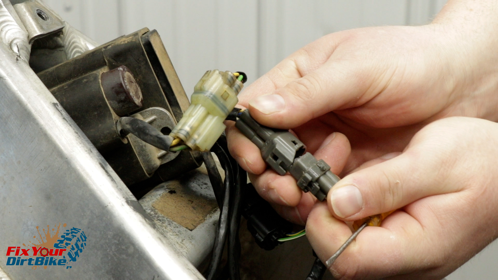


 I wanted to use my CR250 as an example of a fully functioning ignition system. As it turns out, sometime in the past month, my ignition coil died, so that’s good, timing?