How To Rebuild The Front Master Cylinder On Your 1994 – 2001 Yamaha YZ125
The front master cylinder design on your Yamaha YZ125 had some slight redesigns between 1994 and 2001, but the same service applies to all model years.
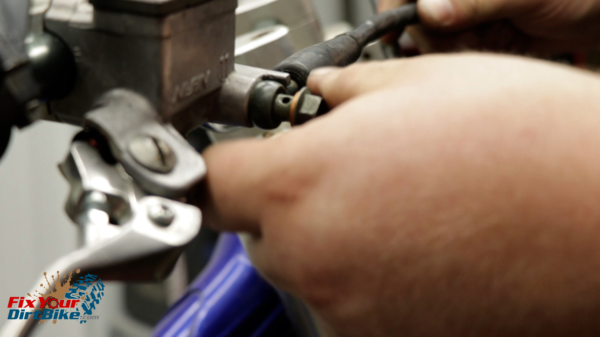
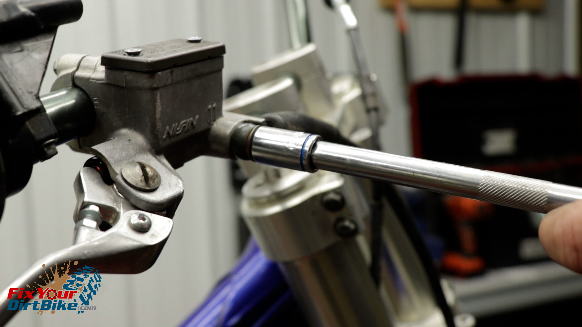
My bike is stripped, so I am removing the banjo bolt on the bench, but I would recommend removing yours while still mounted to the bike.
Brake fluid can damage almost everything, so keep your shop towels handy.
The Tools You Will Need
5mm Hex Wrench
Calipers
Philips Screwdriver
Flathead Screwdriver
Picks
12mm Socket
10mm Socket
Pliers
Electrical Tape
Snap Ring Pliers
The Parts You Will Need
The parts you will need are a front master cylinder rebuild kit, rubber grease, and a fresh bottle dot four brake fluid.
If you don’t have parts yet, you can get all the parts you need HERE!
Unbolt the banjo bolt and wrap the end of the brake line in a paper towel.
Remove the reservoir cap and drain the master cylinder.
My cap screws were stripped out, so I had to use a bolt extractor.
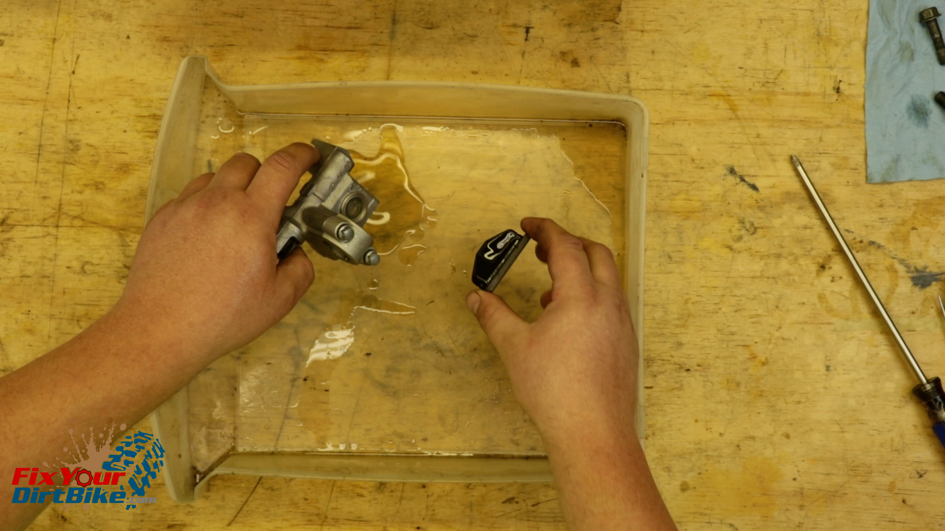
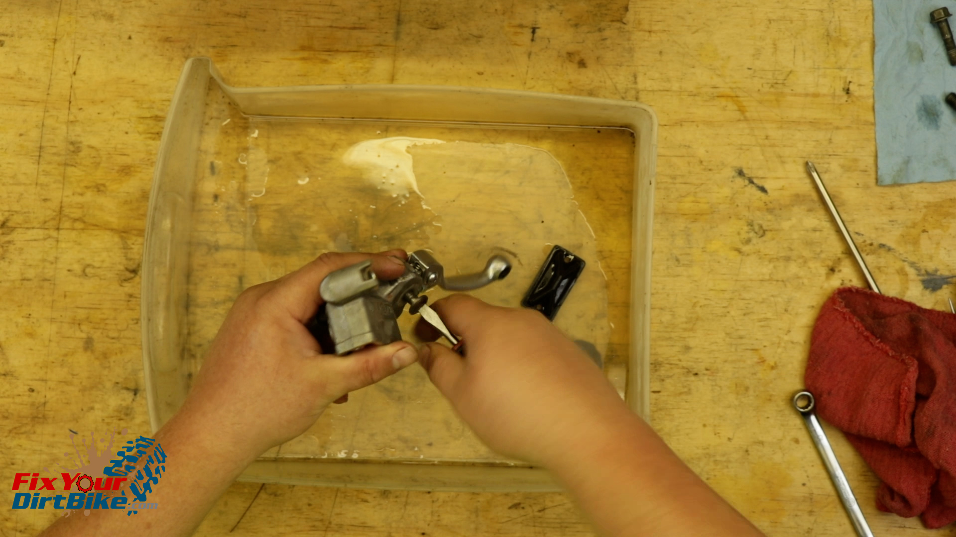
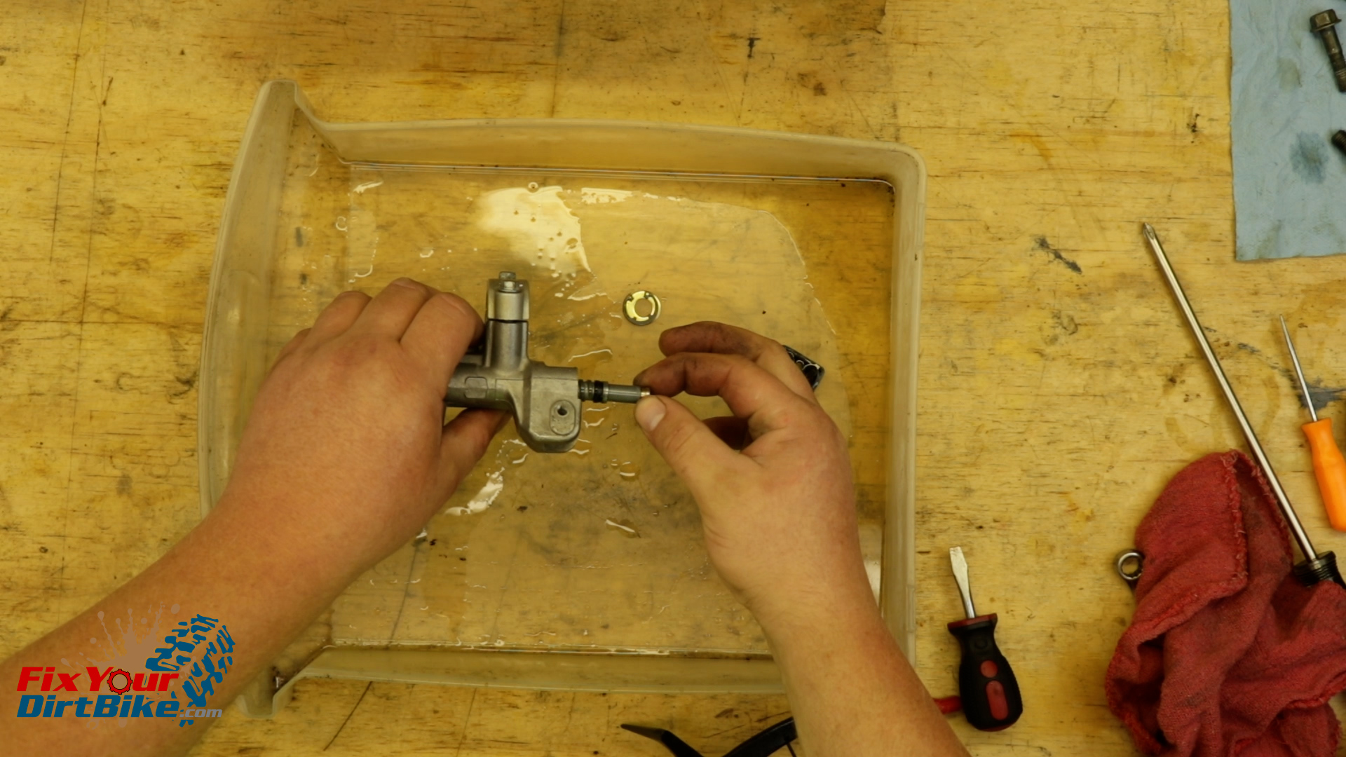
Completely disassemble the master cylinder, starting with the brake lever.
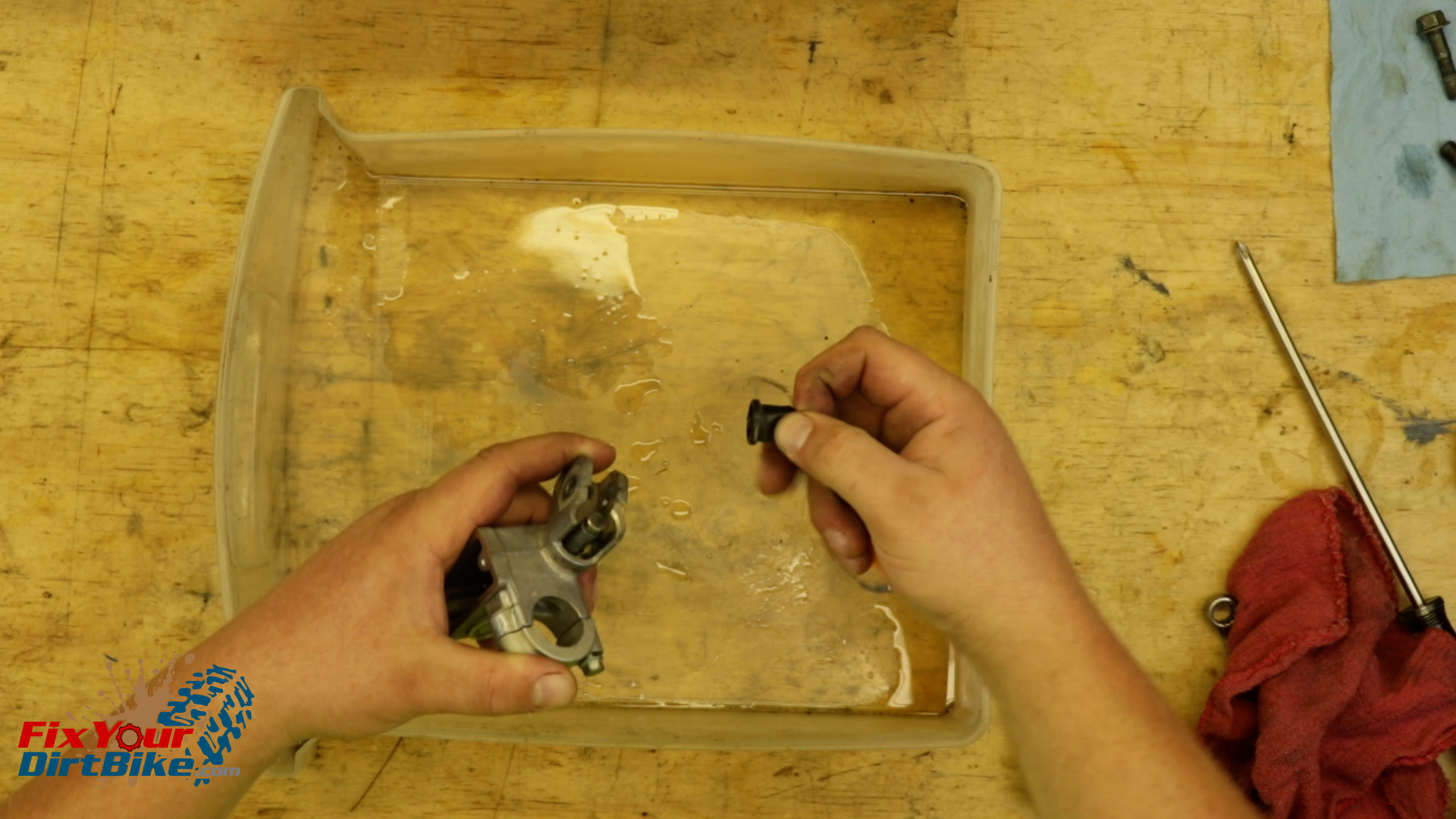
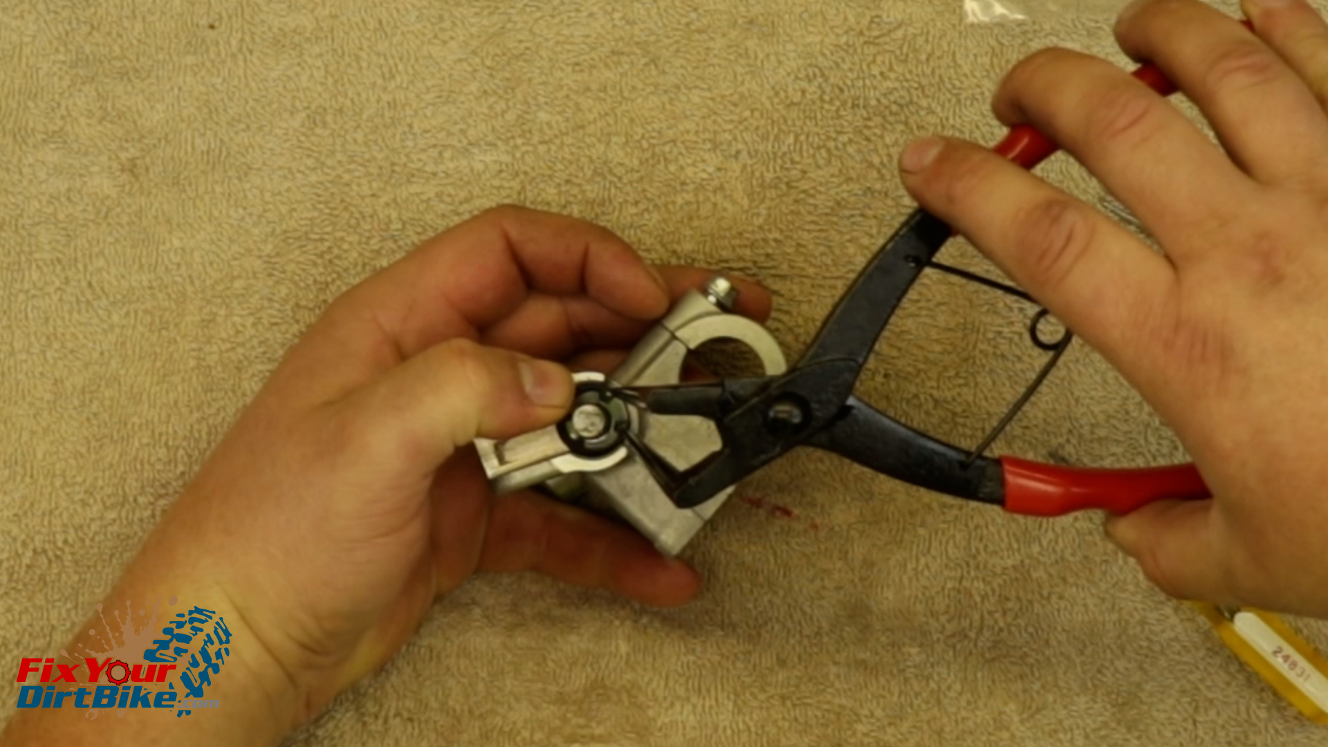
Remove the piston boot.
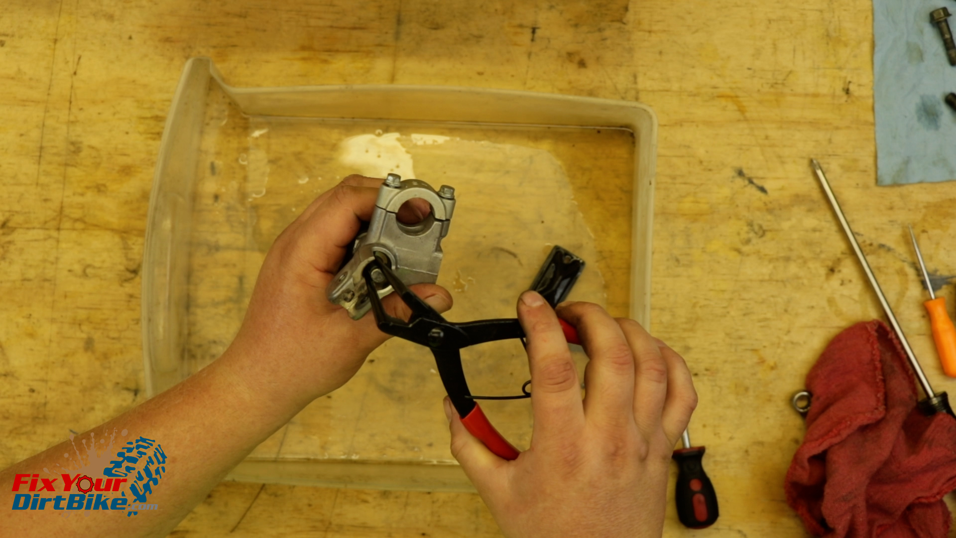
Remove the snap ring retaining the piston with a pair of long nose snap ring pliers or picks.
Pull the piston from the housing.
Unbolt the banjo bolt and wrap the end of the brake line in a paper towel.Remove the reservoir cap and drain the master cylinder.Completely disassemble the master cylinder, starting with the brake lever.Remove the piston boot.Remove the snap ring retaining the piston with a pair of long nose snap ring pliers or picks.Pull the piston from the housing.
Clean & Inspect
Clean all of your front master cylinder components, and make sure to rinse and dry them thoroughly.
As you clean, inspect the components for excessive wear, pitting, and corrosion.
If any piece is damaged, you will need to replace it.
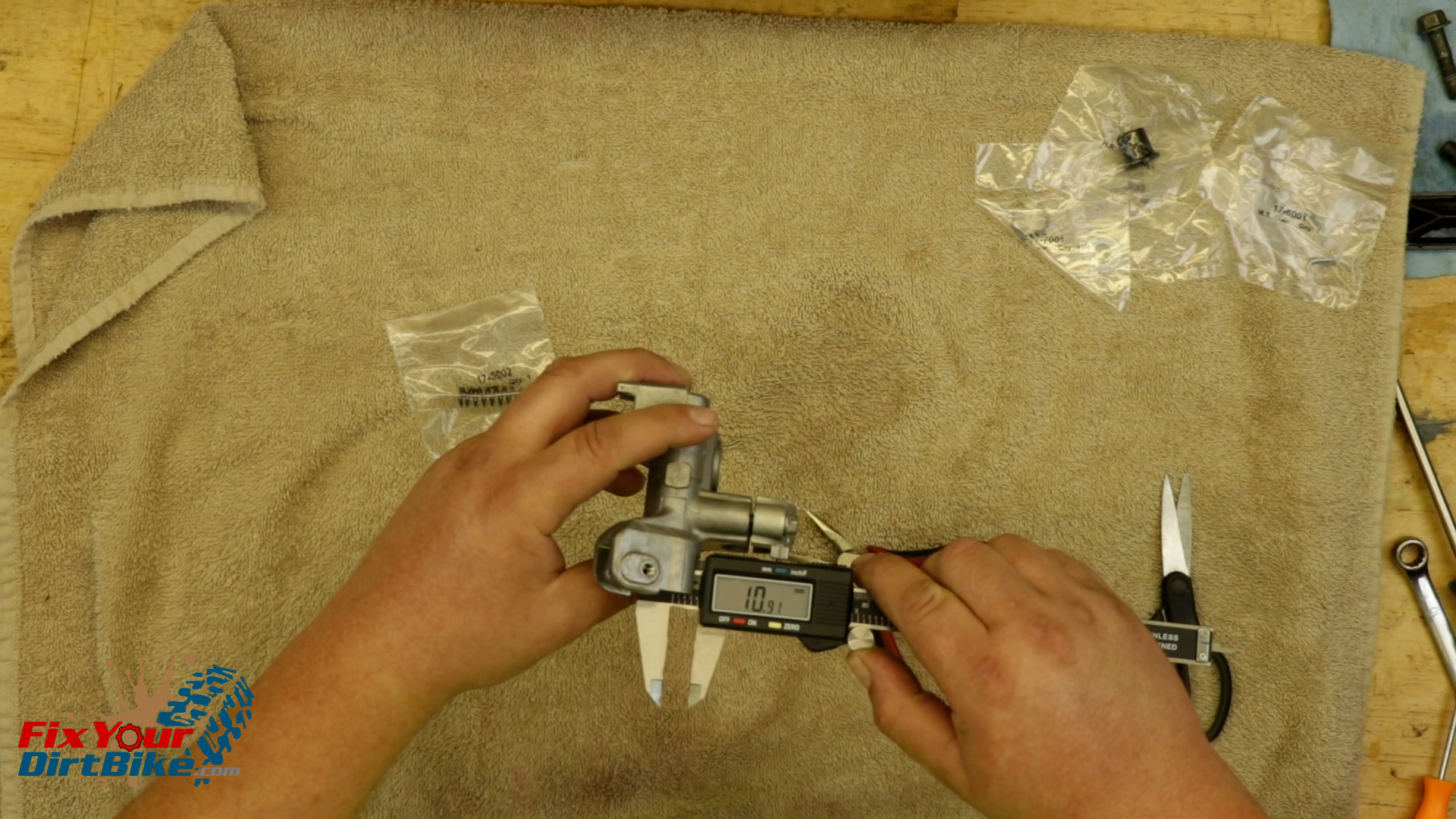
Measure the inside diameter of the cylinder bore.
The cylinder bore should measure no greater than 11mm.
My cylinder bore is just under the service limit at 10.77mm, so my master cylinder is good to go.
The cylinder bore should measure no greater than 11mm.
New Parts
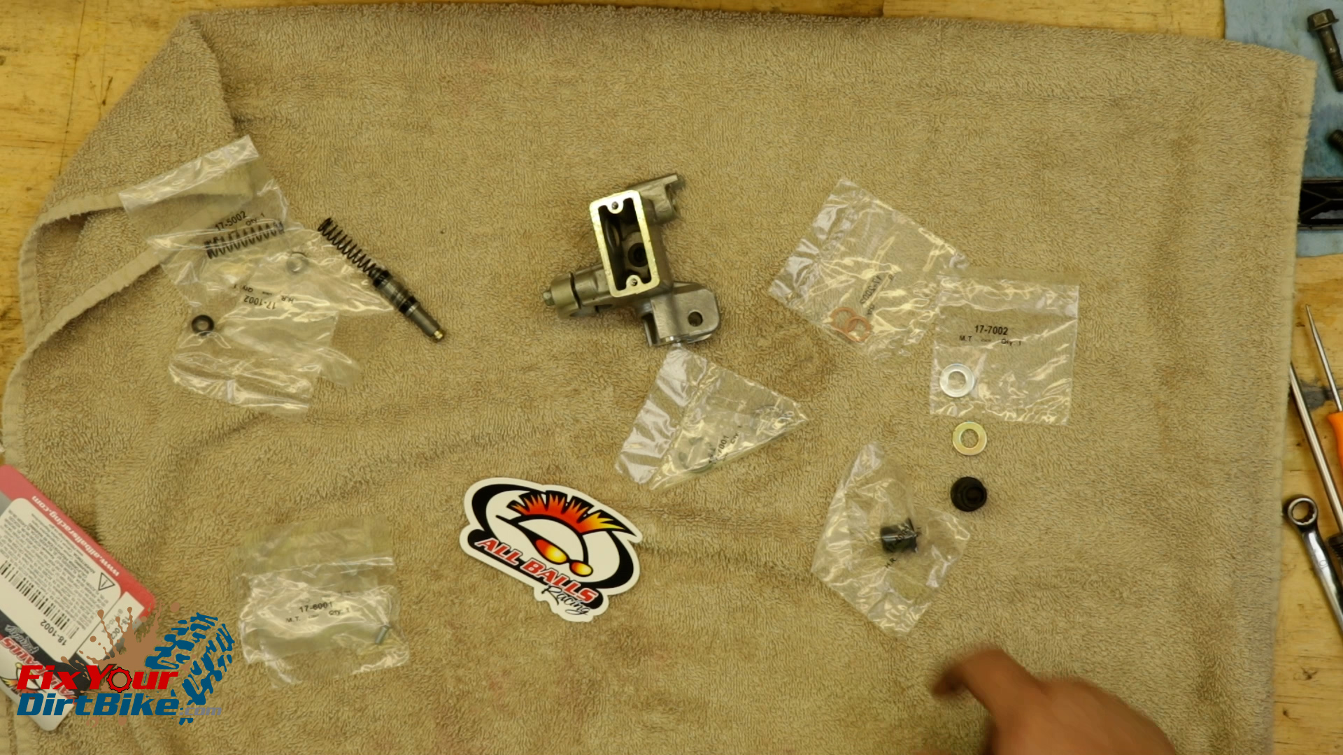
I am installing an All Balls FRONT master cylinder rebuild kit, and you can get this same kit through the link below.
Match the old parts with the new parts to make sure you’re not accidentally throwing away something you need.
Once you have your new parts ready, soak your new piston cups in fresh brake fluid for 15 minutes to soften and lubricate for assembly.
Match the old parts with the new parts to make sure you’re not accidentally throwing away something you need.
Master Cylinder Assembly
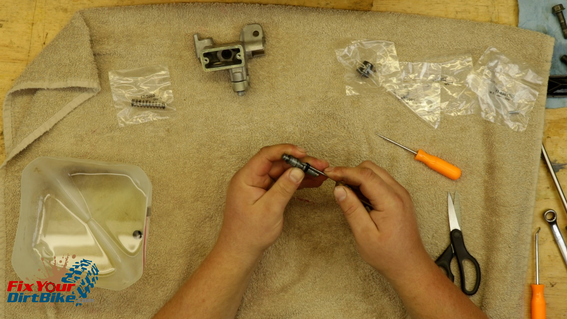
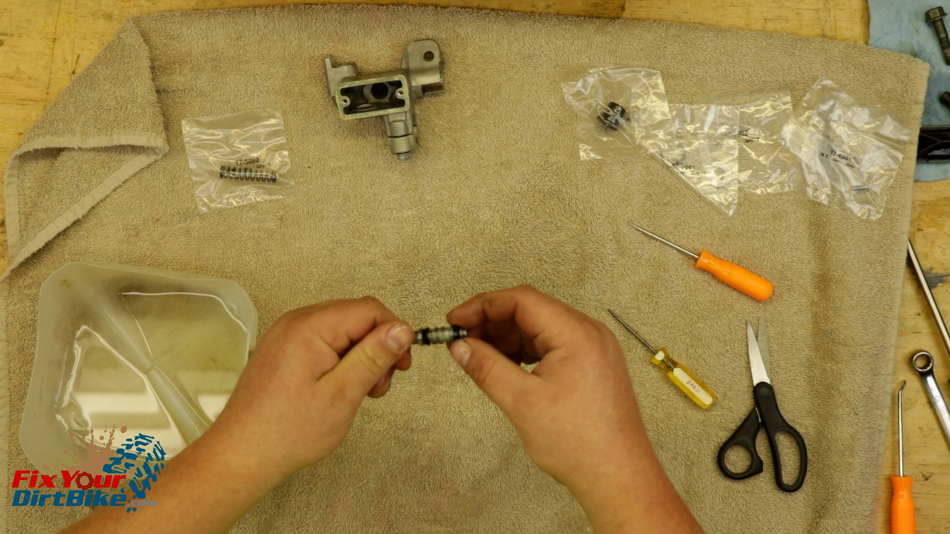
Start your assembly with the piston.
The piston cups are different sizes, so install them in their matching grooves.
Make sure to install the cups, so the wide side is facing the spring end.
Fitting the piston cups over the piston can be a hassle, so take your time and use plenty of brake fluid.
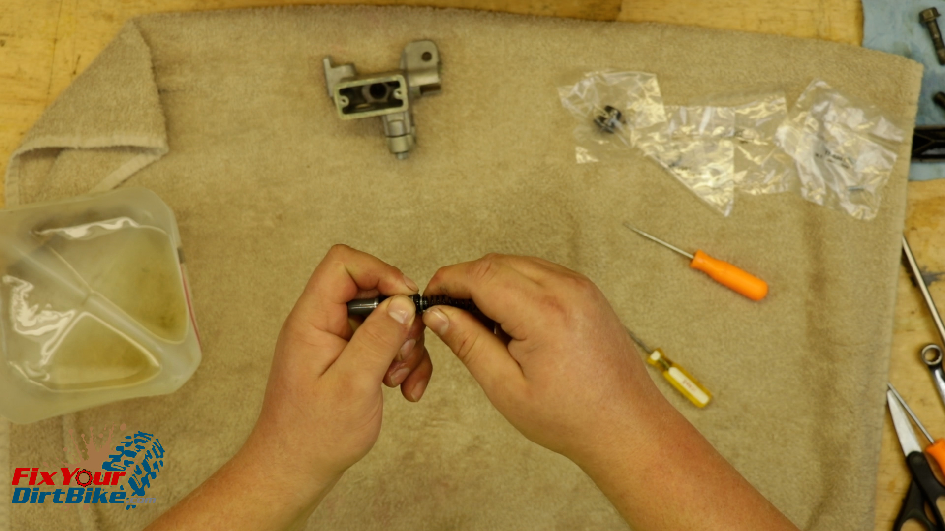
Attach the new spring.
Double-check the cylinder bore for any debris or water leftover from cleaning.
Install the piston past the first cup in a twisting motion and stop when the spring touches the cylinder’s end.
The piston and cylinder are a very tight fit, so make sure not to roll the piston cups on the way in.
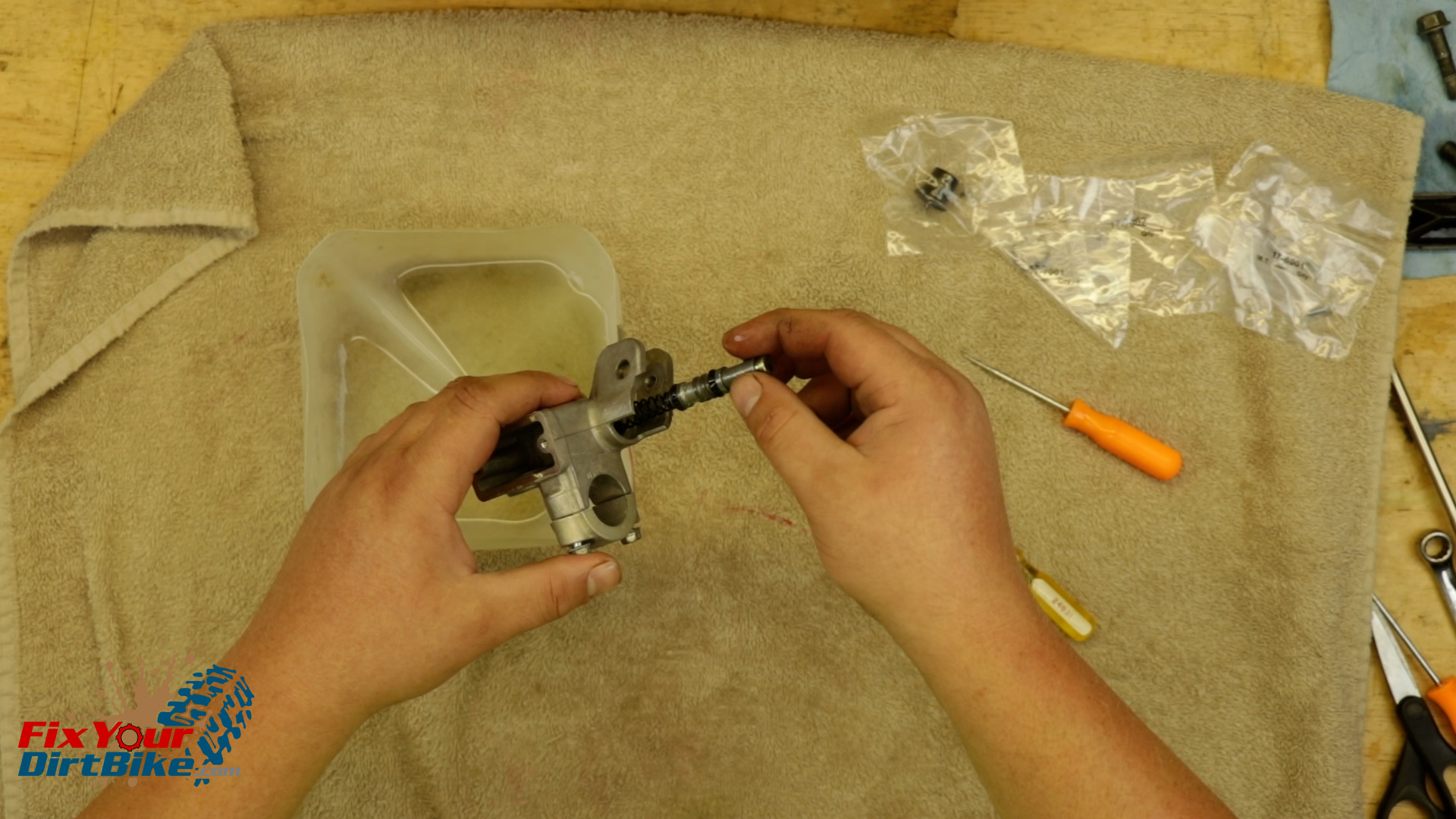
Place the piston washer and spring clip on the piston.
The flat side of the spring clip must face OUT.
With your piston washer and spring clip in position, hold the master cylinder in one hand and carefully press the piston into the bore with your thumb.
While holding the piston down, seat the washer, and install the spring clip.
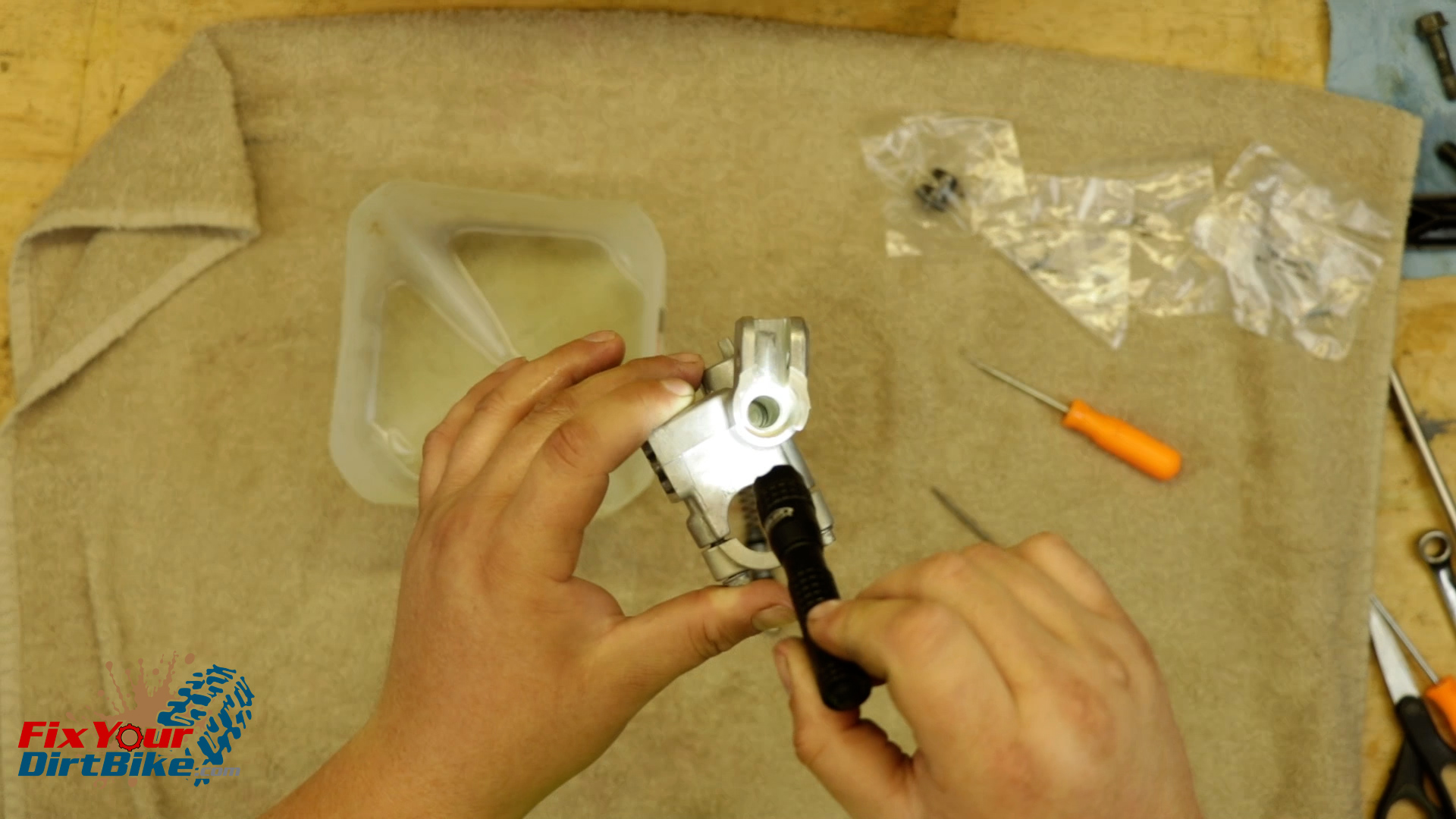
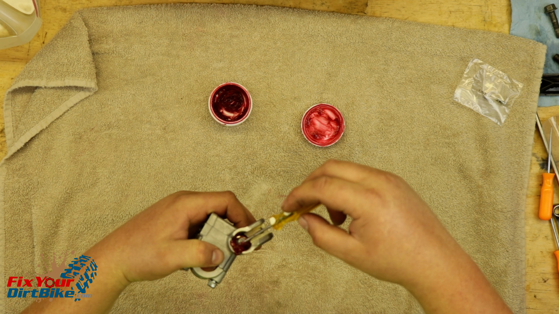
Grease and install the piston boot.
Now isn’t the time to be stingy with the grease, so pack in as much as you can.
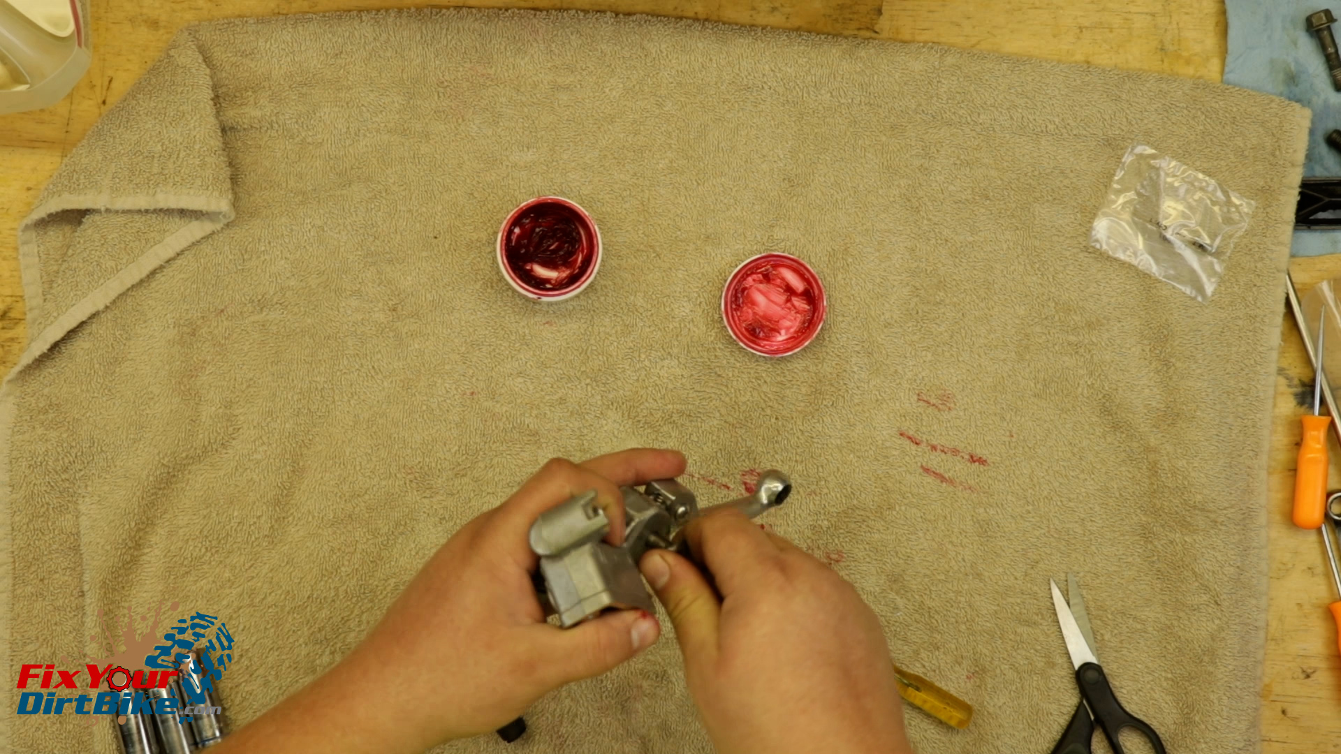
You can use a socket or the round end of a small wrench to push the boot’s sides into the bore.
Whatever you end up using, the boot needs to seat in the groove above the spring clip.
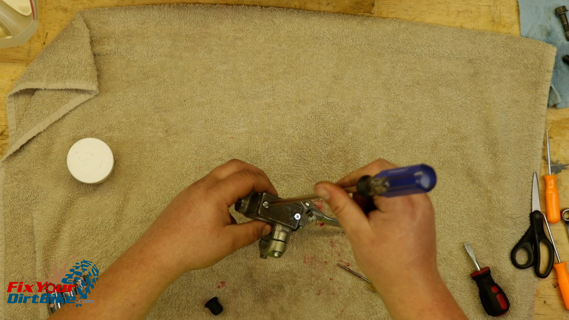
Install the brake lever and test the piston action.
If the action is anything other than smooth, you will need to disassemble the master cylinder and double-check everything.
Install the reservoir cap with new screws.
The piston cups are different sizes, so install them in their matching grooves.Make sure to install the cups, so the wide side is facing the spring end.Attach the new spring.Double-check the cylinder bore for any debris or water leftover from cleaning.Install the piston past the first cup in a twisting motion and stop when the spring touches the cylinder’s end.While holding the piston down, seat the washer, and install the spring clip.Grease and install the piston boot.Install the brake lever and test the piston action.Install the reservoir cap with new screws.
Rear Master Cylinder Install
Mount the master cylinder, and install the banjo bolt with the new seal washers.
Torque the banjo bolt to 25 foot-pounds.
Mount the master cylinder, and install the banjo bolt with the new seal washers.Torque the banjo bolt to 25 foot-pounds.
You can follow me at Fix Your Dirt Bike across all social media, and If you have any questions, please let me know in the comments or direct message!
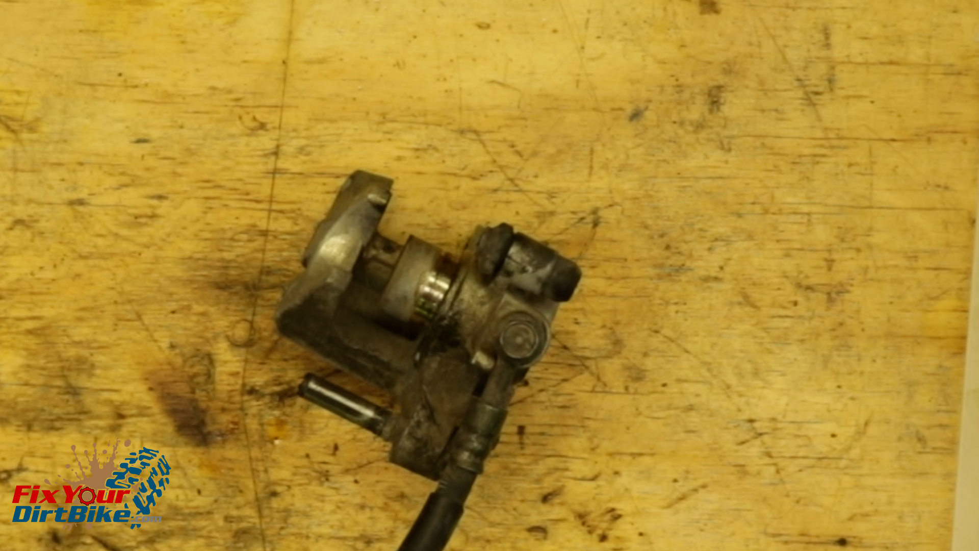
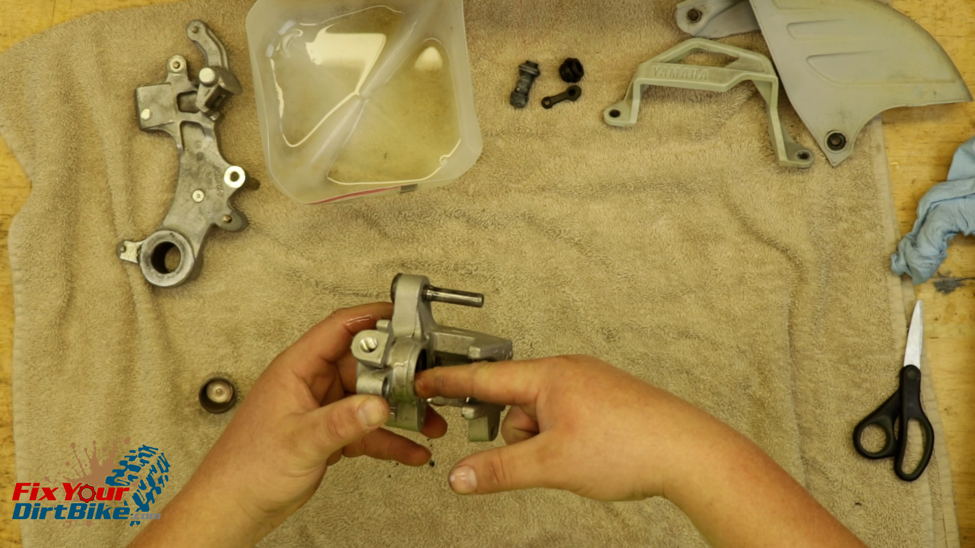
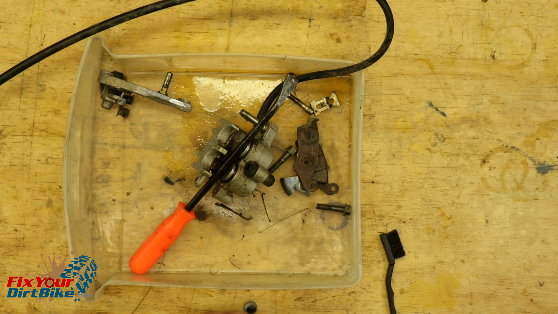
Remove the caliper guard, then Pump the brake pedal to extend the piston out of the caliper body.
With the piston extended as far as possible, remove the banjo bolt.
Wrap the end of your brake line in a shop towel.
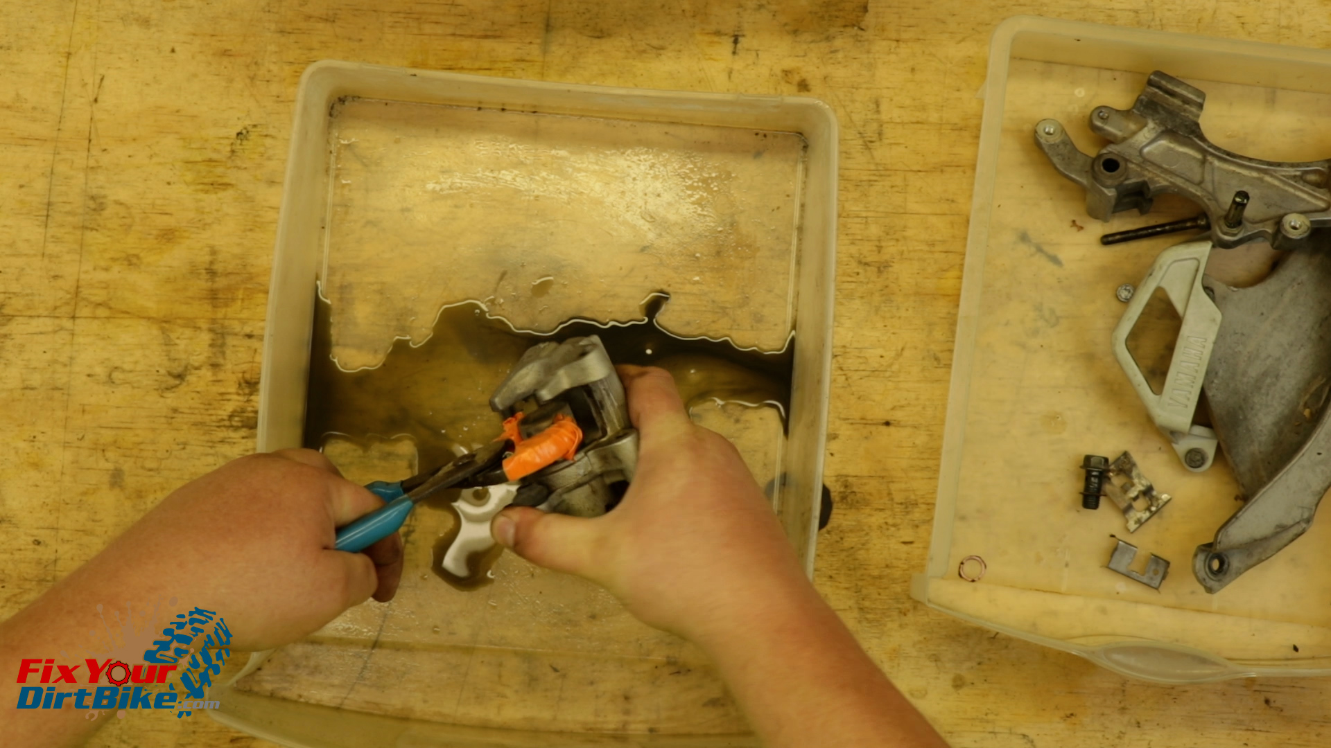
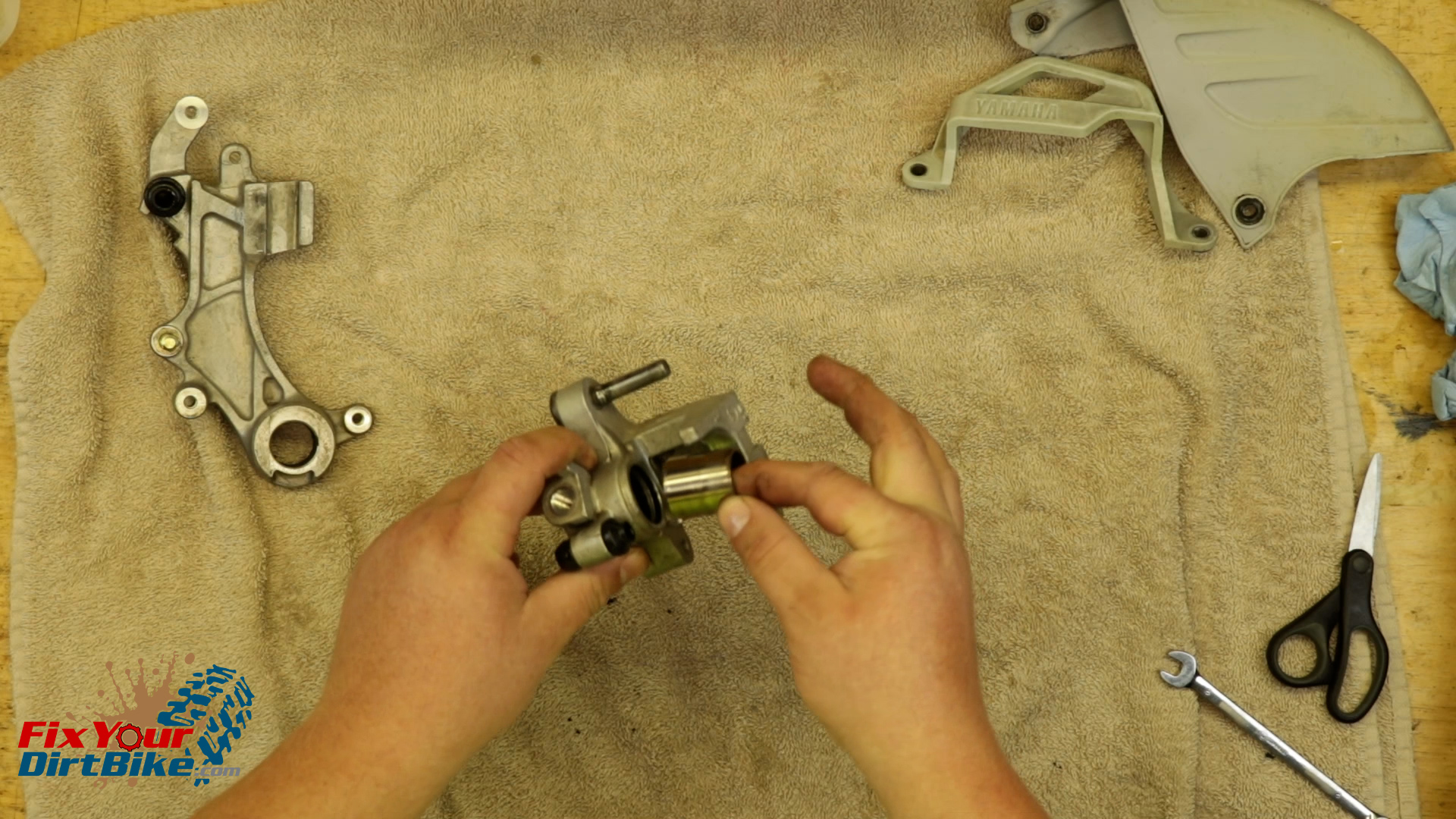
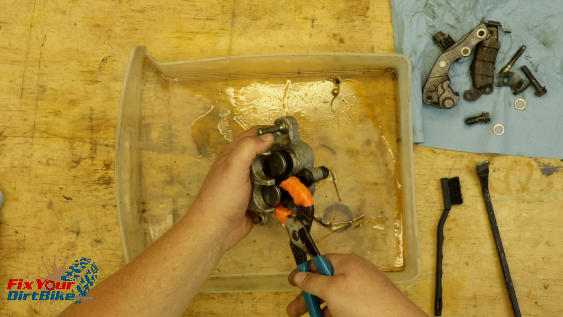
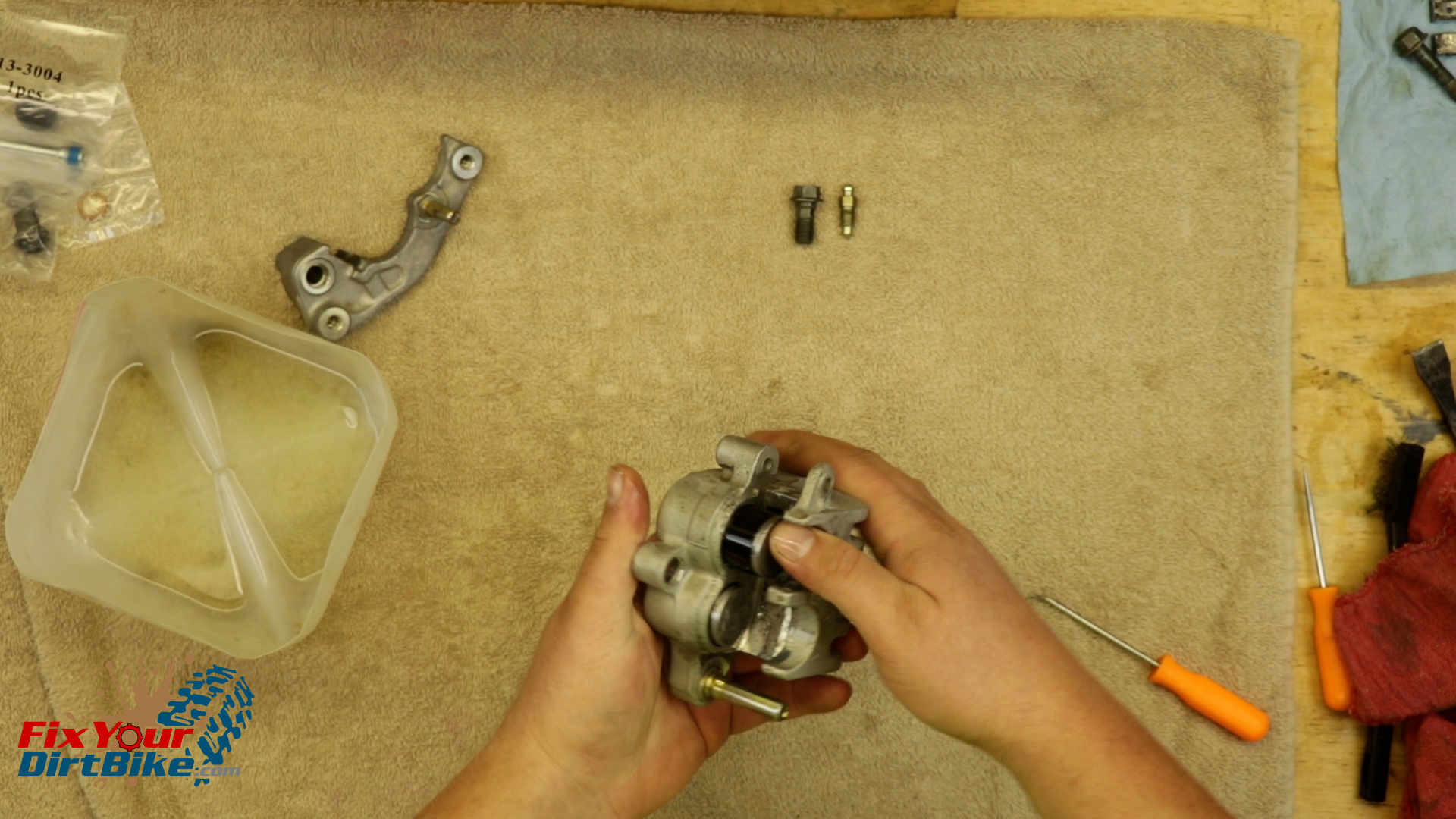
Wrap a pair of pliers in electrical tape, and pull the piston out of the caliper in a twisting motion.
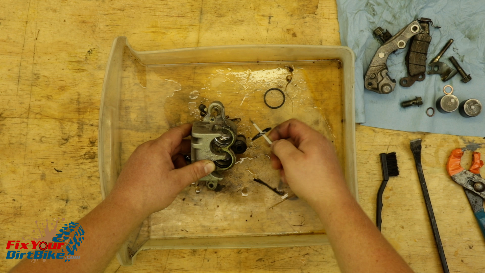
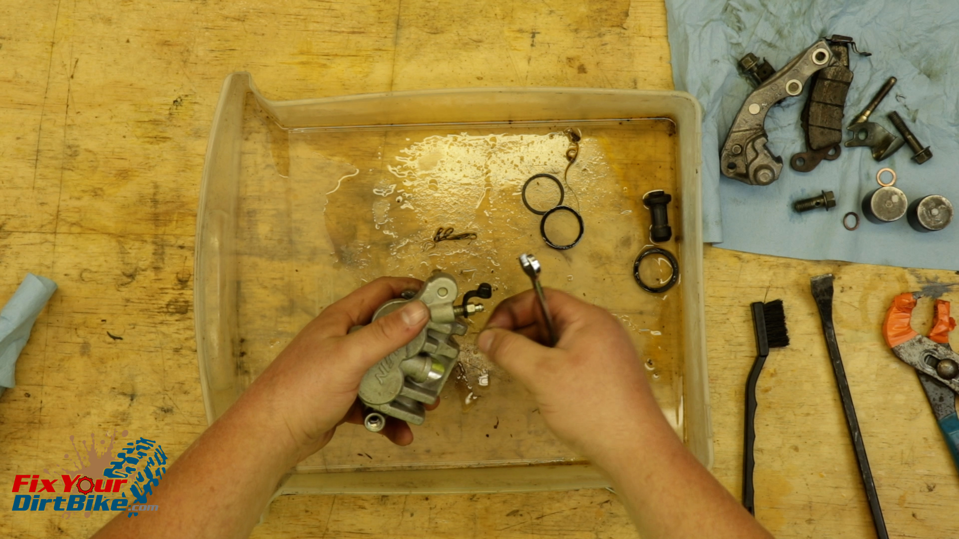
Remove the slide boots from the caliper and bracket, followed by the bleeder valve and piston seals.
My piston bore was extremely dirty, so I had to clean it before removing the piston seals.
Remove the caliper guard, then Pump the brake pedal to extend the piston out of the caliper body.With the piston extended as far as possible, remove the banjo bolt.Wrap a pair of pliers in electrical tape, and pull the piston out of the caliper in a twisting motion.Remove the slide boots from the caliper and bracket, followed by the bleeder valve and piston seals.My piston bore was extremely dirty, so I had to clean it before removing the piston seals.
Clean & Inspect
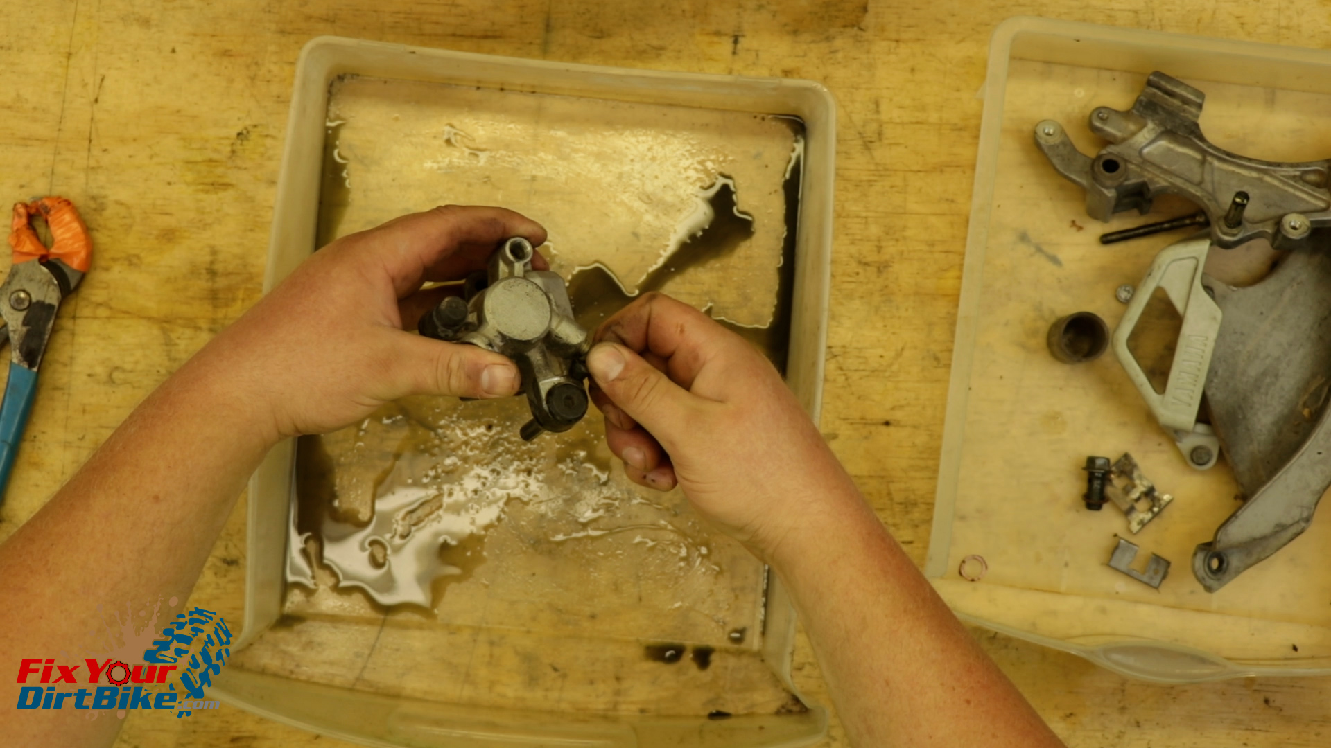
Clean all of your rear caliper components, and make sure to rinse and dry them thoroughly.
Inspect the components for excessive wear, pitting, and corrosion.
If any part is damaged, you will need to replace it.
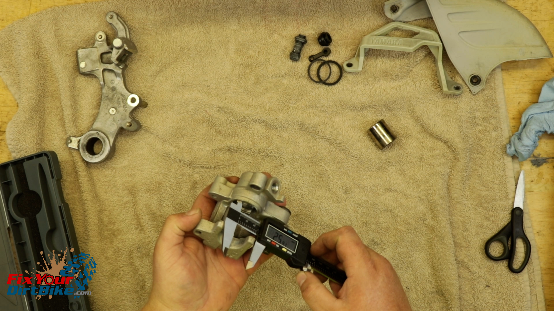
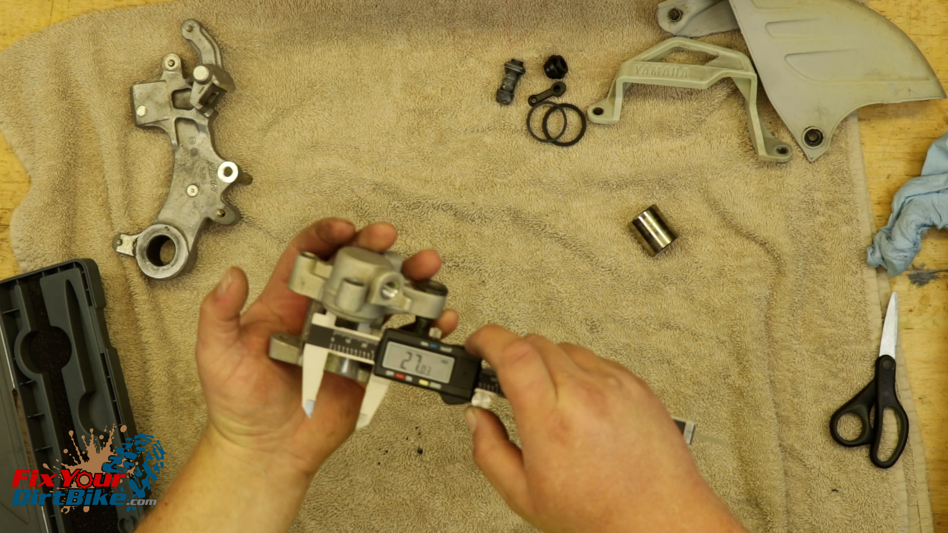
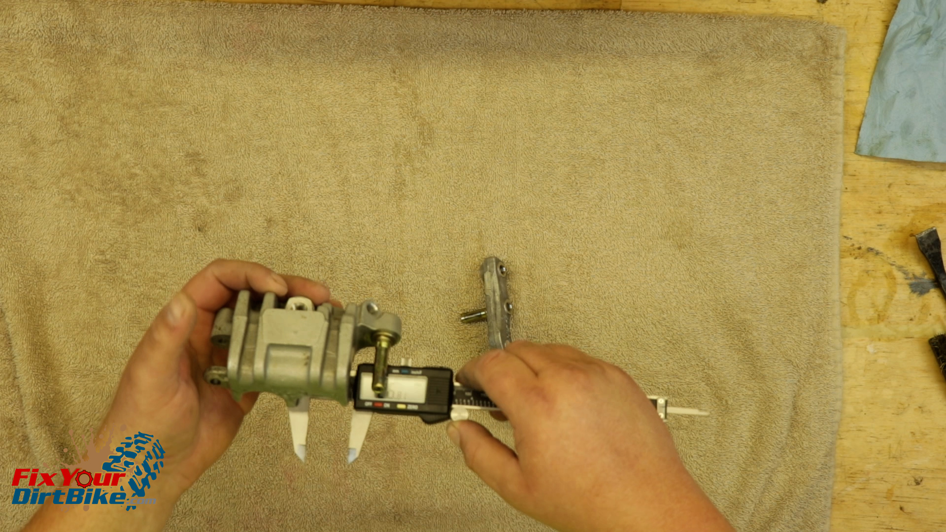
Measure the inside diameter of the piston bore.
The piston bore should be no Greater than 30.23mm on 1994 through 1997 models, and 27mm from 1998 through 2001 models.
My caliper measured out of spec at 27.03 mm, but that’s close enough for me!
Measure the inside diameter of the piston bore.My caliper measured out of spec at 27.03 mm, but that’s close enough for me!
New Parts
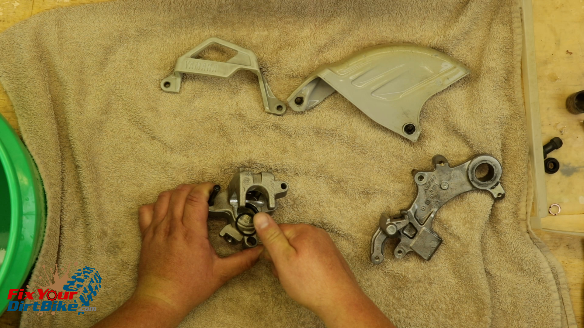
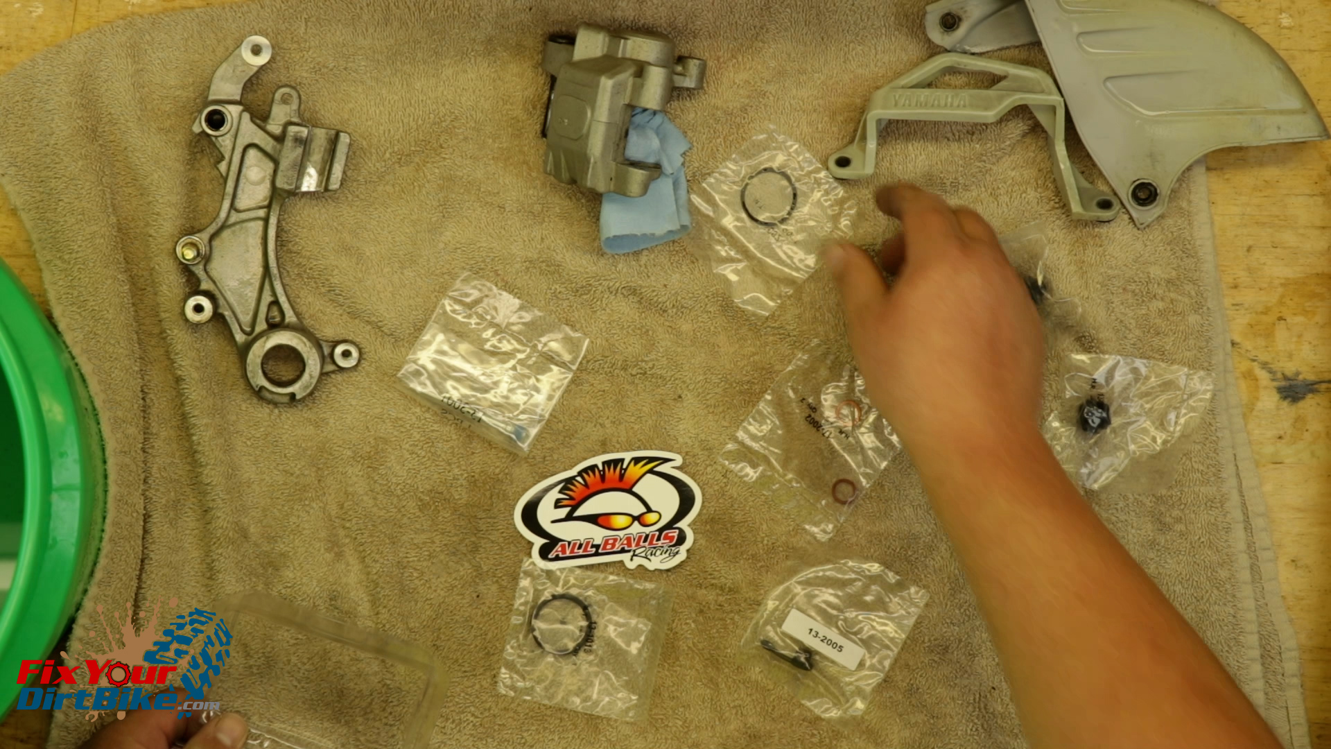
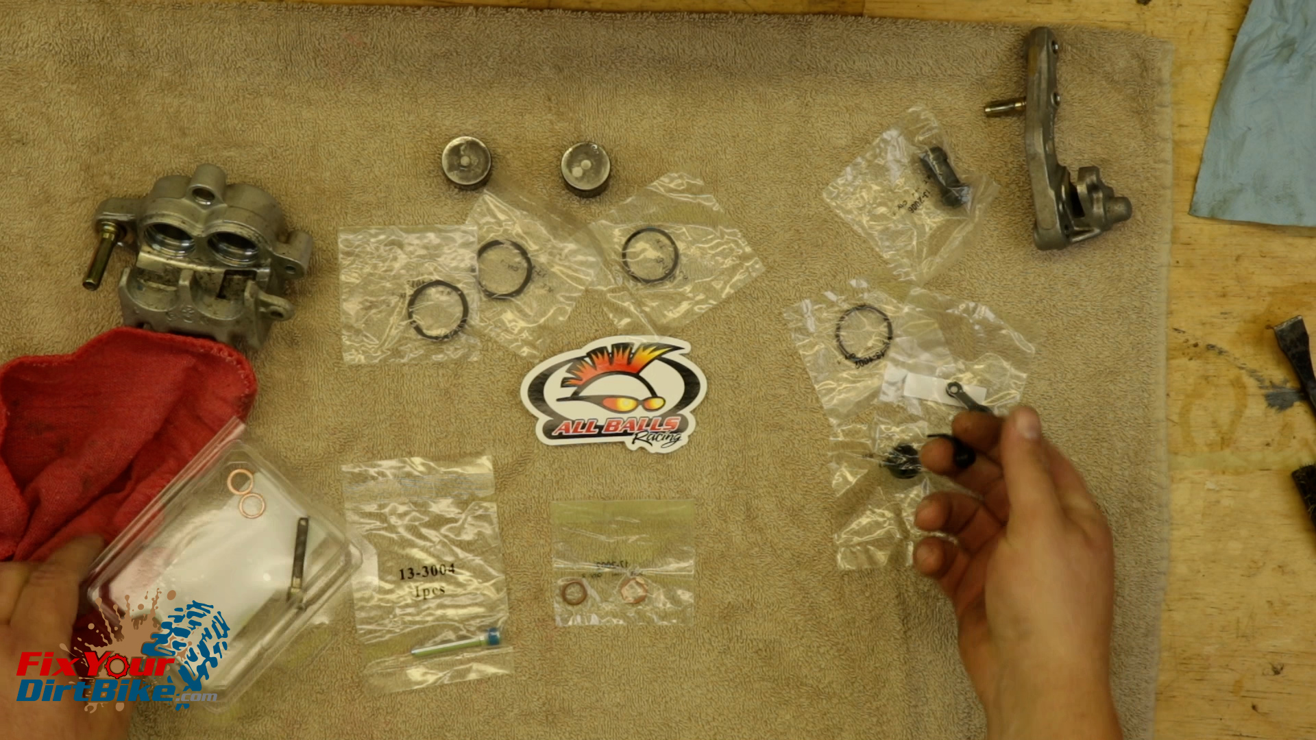
I am installing an All Balls Rear Caliper rebuild kit, and you can get this same kit through the link below.
Match the old parts with the new parts to make sure you’re not accidentally throwing away something you need.
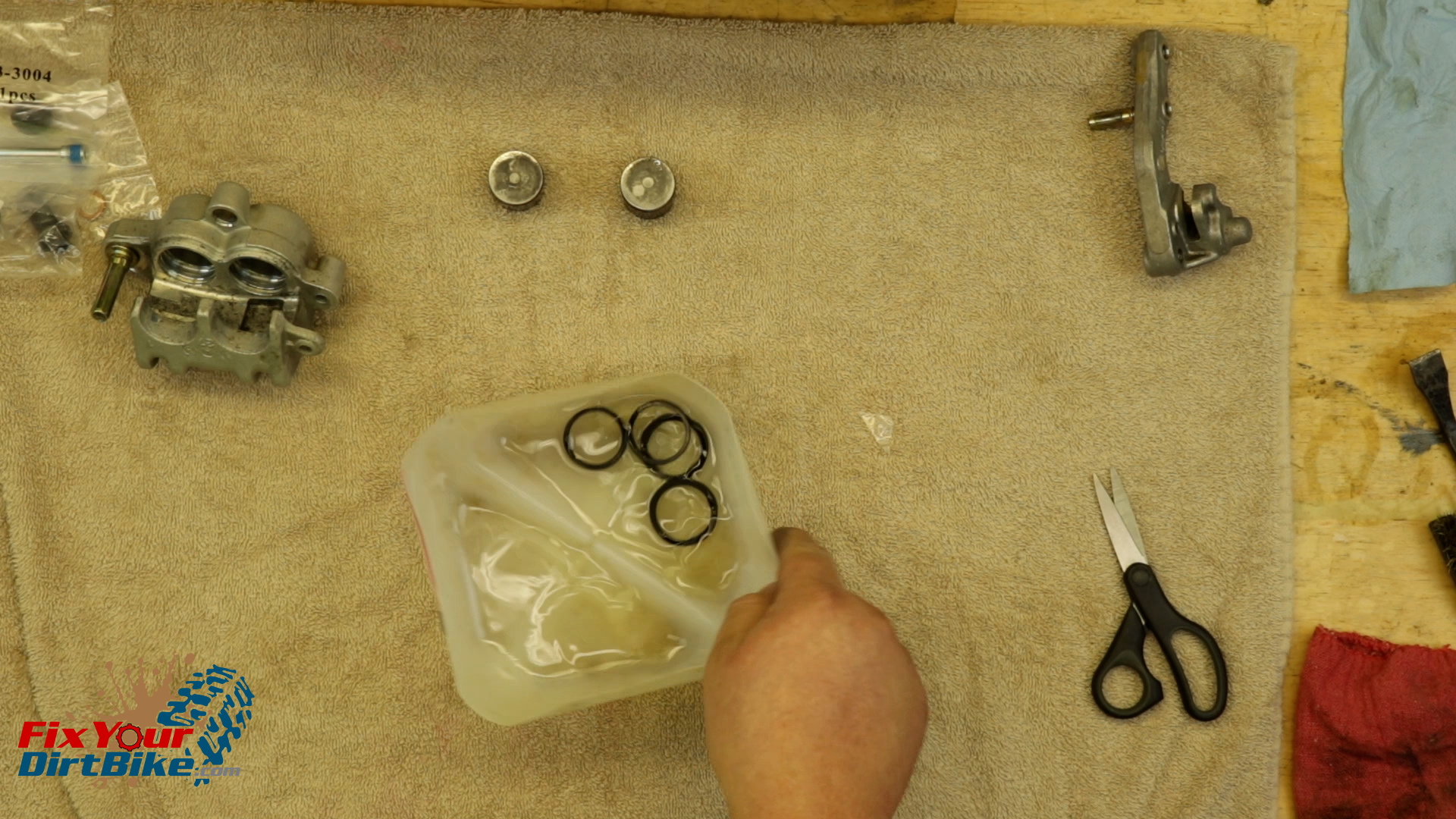
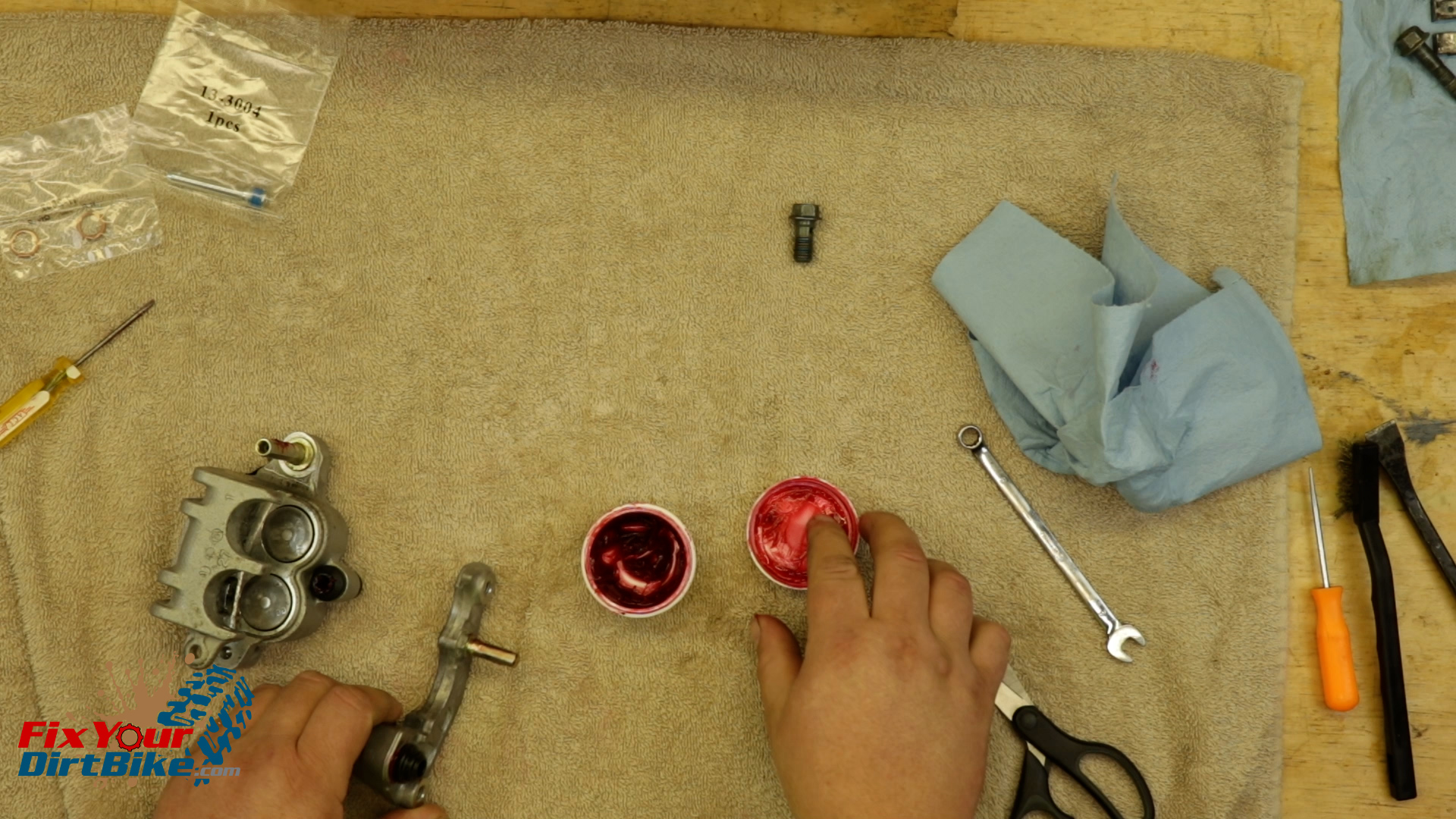
Once you have your new parts ready, soak your new piston seals in fresh brake fluid for 15 minutes to soften and lubricate for assembly.
Match the old parts with the new parts to make sure you’re not accidentally throwing away something you need.Once you have your new parts ready, soak your new piston seals in fresh brake fluid for 15 minutes to soften and lubricate for assembly.
Caliper Assembly
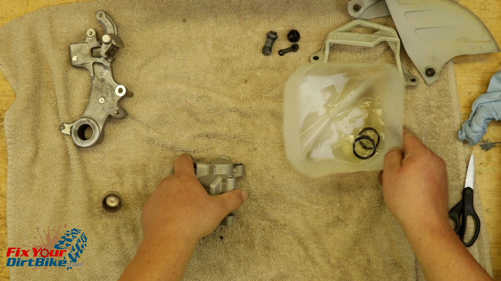
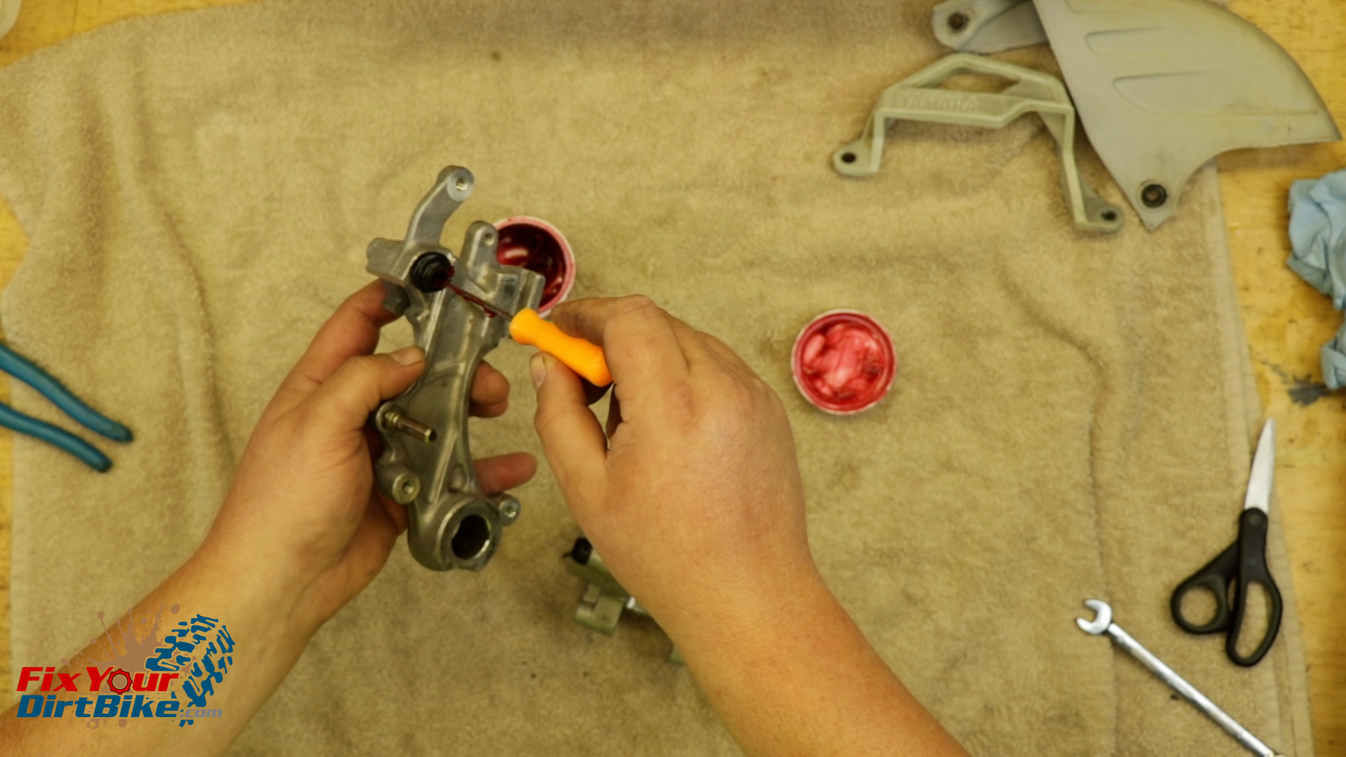
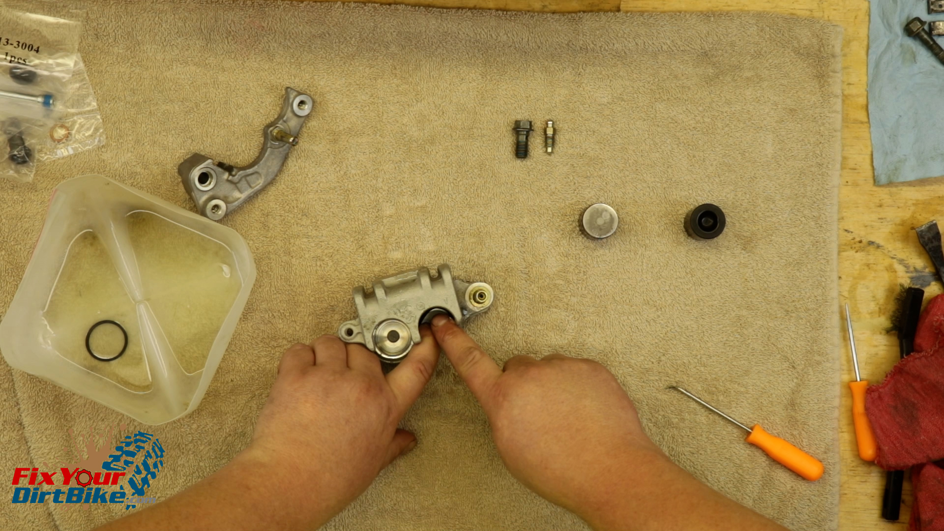
Start by installing your new piston seal and dust seal.
Install the new boots. The long boot goes on the caliper, and the short boot goes on the bracket.
Install the new bleeder valve cap, then install the bleeder valve.
Coat the piston in brake fluid, then install the piston in a twisting motion with the open end facing OUT.
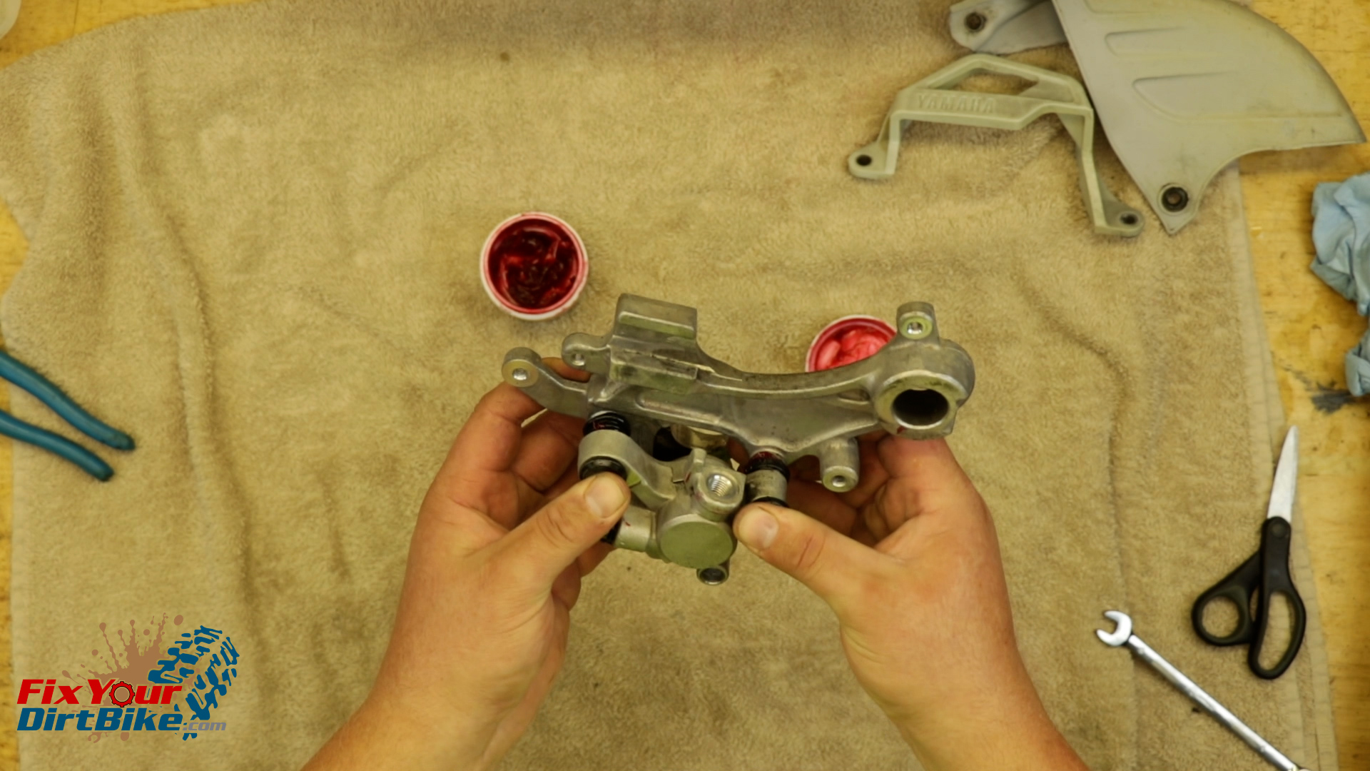
Grease the slide pin boots and slide pins, get as much grease as you can into the boots.
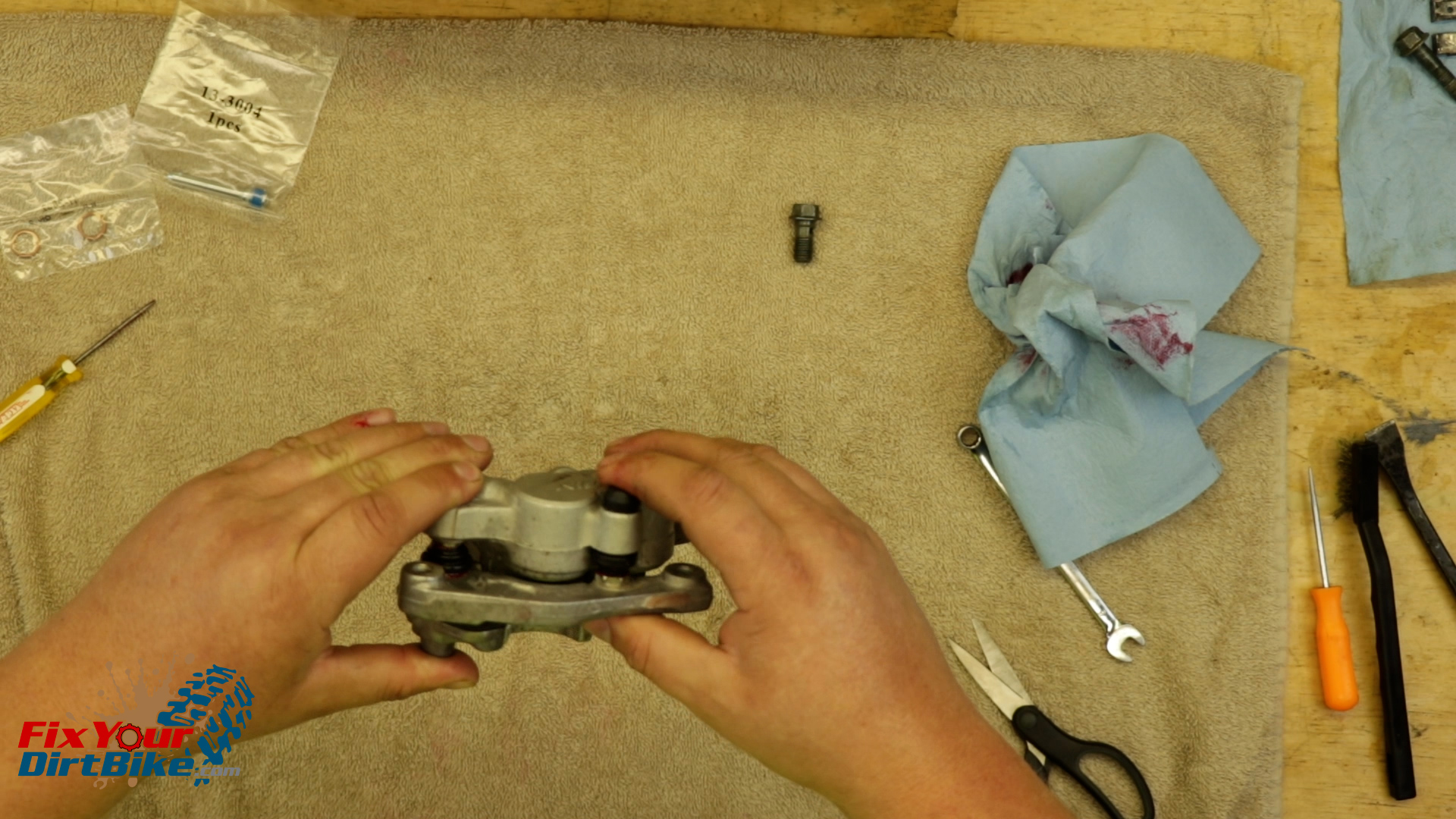
Assemble the bracket and body, then give the bracket a few pumps to evacuate any trapped air in the boots.
Start by installing your new piston seal and dust seal.Coat the piston in brake fluid, then install the piston in a twisting motion with the open end facing OUT.Grease the slide pin boots and slide pins, get as much grease as you can into the boots.Assemble the bracket and body, then give the bracket a few pumps to evacuate any trapped air in the boots.
Rear Caliper Install
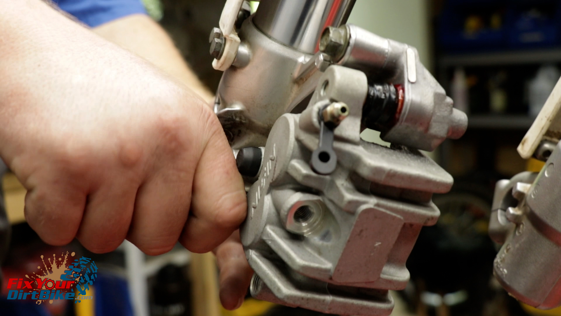
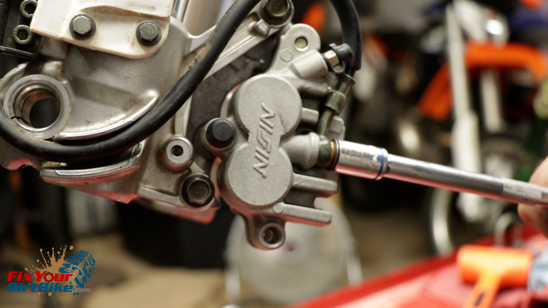
Install the banjo bolt with new seal washers.
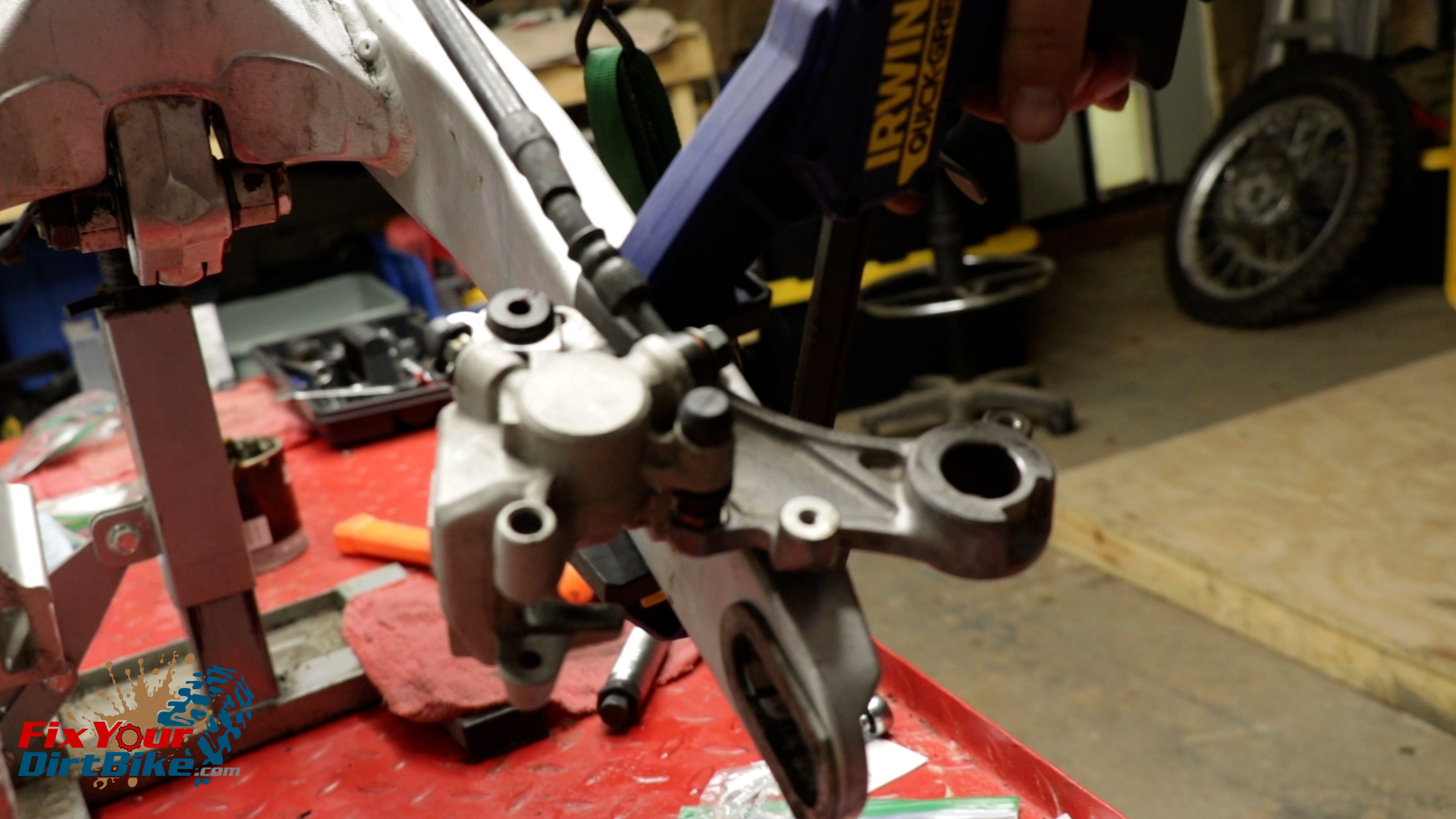
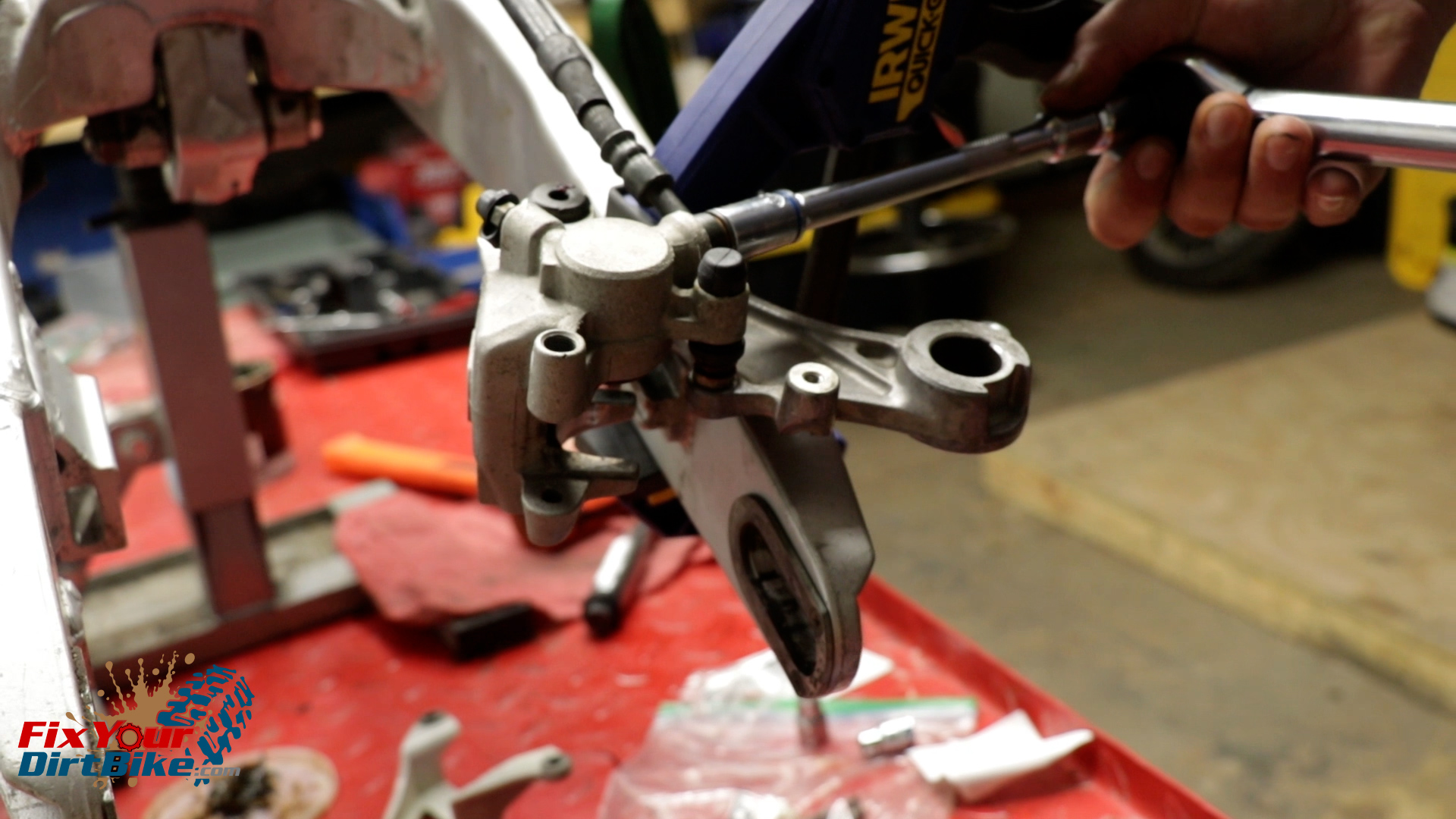
As you will see, you can’t access the banjo bolt with a torque wrench when installed on the swingarm. So clamp the caliper bracket to the top of the swingarm.
Torque the banjo bolt to 25 foot-pounds.
As you will see, you can’t access the banjo bolt with a torque wrench when installed on the swingarm. So clamp the caliper bracket to the top of the swingarm.Torque the banjo bolt to 25 foot-pounds.
You can follow me at Fix Your Dirt Bike across all social media, and If you have any questions, please let me know in the comments or direct message!
Start by removing your front wheel and brake pads.
Pump the brake lever to extend the pistons as far as possible.
Place something flat against the pistons, so they extend evenly from the caliper body.
When the pistons have reached full extension, remove the banjo bolt, and wrap the end of your brake line with a paper towel.
Remove the caliper from the fork.
Pump the brake lever to extend the pistons as far as possible.Place something flat against the pistons, so they extend evenly from the caliper body.
Caliper Disassembly
Wrap a pair of pliers in electrical tape, and pull the pistons out of the caliper in a twisting motion.
Carefully remove the seals from the caliper bore.
Remove the slide boots from the caliper and bracket, followed by the bleeder valve.
Wrap a pair of pliers in electrical tape, and pull the pistons out of the caliper in a twisting motion.Carefully remove the seals from the caliper bore.Remove the slide boots from the caliper and bracket, followed by the bleeder valve.
Clean & Inspect
Clean all of your front caliper components, and make sure to rinse and dry them thoroughly.
Inspect the components for excessive wear, pitting, and corrosion.
If any part is damaged, you will need to replace it.
Measure the inside diameter of the piston bore.
The piston bore should be no Greater than 27mm.
My caliper was within spec at 26.83mm, so it’s good to go.
Measure the inside diameter of the piston bore.
New Parts
I am installing an All Balls Front Caliper rebuild kit, and you can get this same kit through the link below.
Match the old parts with the new parts to make sure you’re not accidentally throwing away something you need.
Once you have your new parts ready, soak your new piston seals in fresh brake fluid for 15 minutes to soften and lubricate for assembly.
Match the old parts with the new parts to make sure you’re not accidentally throwing away something you need.Once you have your new parts ready, soak your new piston seals in fresh brake fluid for 15 minutes to soften and lubricate for assembly.
Caliper Assembly
Install the piston seals and dust seals.
Coat your pistons in brake fluid, and install them in a twisting motion.
Install the bleeder valve cover, then the bleeder valve.
Install the slide pin boots.
The short boot goes on the bracket, and the long boot goes on the body.
Grease the slide pin boots and slide pins, get as much grease as you can into the boots.
Assemble the bracket and body, then give the bracket a few pumps to evacuate any trapped air in the boots.
Install the piston seals and dust seals.Coat your pistons in brake fluid, and install them in a twisting motion.Grease the slide pin boots and slide pins, get as much grease as you can into the boots.Assemble the bracket and body, then give the bracket a few pumps to evacuate any trapped air in the boots.
Front Brake Caliper Install
Install your caliper on the fork, then route the brake line.
Install your banjo bolt with the new seal washers.
Torque the banjo bolt to 25 foot-pounds, and the mounting bolts to 17 foot-pounds.
Install your caliper on the fork, then route the brake line.Torque the banjo bolt to 25 foot-pounds, and the mounting bolts to 17 foot-pounds.
You can follow me at Fix Your Dirt Bike across all social media, and If you have any questions, please let me know in the comments or direct message!
Over the years, motorcycle builders have come up with multiple methods of keeping valves within adjustment for as long as possible before needing to adjust lash.
With each passing model generation, more and more bikes turned to a shim-under-bucket configuration. But why? Let’s explore why poppet valves (mushroom valves) need to be adjusted to stay within spec, and what made shims and buckets the (might as well be) industry standard.
Why Do Engine Valves Need To Be Adjusted Periodically?
Valves sit inside the cylinder head, and a stiff spring holds them tight against the valve seat on the explody side of the head. Valves perform two duties: Seal the combustion chamber, and move air in and out of the cylinder.
The camshaft regulates when the valves open (and close) with its lobes. Camshafts control valve operation in both overhead cam and pushrod/rocker designs. This type of valve only applies to 4-stroke Motorcycle engines. 2-stroke is an entirely different engine design (and way more fun, fight me in the comments!)
When the valve closes, it seats against a beveled edge called a valve seat. Valve seats are typically a hardened insert, some of which can be changed; others are welded in and need extensive machining to repair. Dirt bikes need this valve seat insert because most manufacturers use aluminum heads, and the constant hot slap-slap-slap-slap-slap-slap-slap-slap-slap-slap-slap-slap-slap-slap-slap-slap-slap-slap-slap-slap-slap-slap-slap-slap against the soft aluminum would brick a cylinder head almost immediately.
Valves are metal; metal conducts heat, too much heat is terrible for combustion. Valves act as a heat sink to pull heat away from the combustion chamber. Heat dissipation is why the exhaust valve is usually larger than the intake; more surface area = better heat transfer away from the cylinder. On high-performance auto engines, you will typically see sodium-filled exhaust valves, because sodium is an excellent heat conductor. But that’s overkill for dirt bikes.
Adjusting the valves is essential because the perpetual slap-and-tickle of the valve against the valve seat makes it recede into the cylinder head. Gone unchecked, the cold end of the valve stem will contact the camshaft lobe or rocker arm. If the valve seat is worn enough, and valve-to-actuator clearance (lash) decreases enough, the valve will stay open, creating two issues.
First, the valve no longer contacts the valve seat, so the heat transfer to the head decreases significantly.
Second, the gap created by an unseated valve lets gases through at high speed. When this valve gap is on the exhaust side, oxygen can enter the engine during every stroke, and cause severe damage when mixed with the superheated gases. The mix of oxygen and heat can melt metal, and that is how you “burn a valve.”
How Many Valve Adjusters Are In Use, And Which One Is The Best?
You can adjust valve lash in multiple ways; some methods are more common than others. Determining which method is the “better” comes down to what you want from the specific motorcycle engine. Is the motor designed for sustained screaming high revs (sportbike), constant RPM changes (dirt bike), or consistent cruising (Road Bikes)? Below you will find the most common valve designs for adjusting and setting valve lash, as well as their respective pros and cons.
Hydraulic Lifters
You will typically see Hydraulic lifters in low-RPM Pushrod V-Twin applications. Hydraulic lifers pressurize the existing engine oil that makes it way inside the lifter body to automatically keep rocker arm and the valve stem clearance in spec. This system makes valve adjustments automatic every time you ride.
Hydraulic lifters are easy to maintain and have been around since before the Harley-Davidson Panhead engine. Hydraulic lifters do an excellent job of automatically setting the valve lash.
But, because they rely on oil pressurization, they take slightly longer to engage the pushrod. The slight lag that hydraulic lifters create is an eon when it comes to high revving motorcycle engines that can spin up to 15,000 RPM.
There is a reason why hydraulic lifers are at home in low RPM applications with redlines around 6,500. One well-known exclusion of this rule is the Honda Nighthawk 700S that peaked at 10,600 RPM! Sick.
Desmodromic Valve System
Desmodromic valves have been around since as early as 1886. In 1956, Dr. Fabio Taglioni developed them for use in racing motorcycles for a little Italian manufacturer called Ducati. Desmo valves do not use springs to keep them seated. Instead, they are directly linked to the camshaft, forcing them to stay in time and eliminating valve float. Since the cam pulls double duty to open and close the valves, they have two clearances to keep within spec.
In the 1950s, valve springs could only handle so much, so the desmodromic valve was an engineering marvel (even though it was an older design). When other motorcycle race engines were peaking at 10,000 PRM, Ducati’s engines could scream to 15,000 RPM! In the 50s!
We’ve come a long way since then, and advances in metallurgical science have made desmodromic valves obsolete. However, they are unique, and they took Ducati from post-war Italy to today, so if it ain’t broke, don’t fix it!
You will never find desmo valves in dirt bikes, but they’re interesting, so they’re on this list. HA, made you read that!
Screw-and-Locknut Valve Adjuster
Screw-and-Locknut were the typical adjustment system in most early Japanese bikes since they almost always had an overhead cam cylinder head design. Locknut adjusters are ideal since all you need are two wrenches and a set of feeler gauges to adjust lash. Loosen the locknut, adjust the set screw, tighten the locknut. That’s it.
Also, since Screw-and-Locknut adjusters are found in low-performance motorcycle engines that are designed for sustained RPM, you don’t have to adjust them too often. You can also adjust your valve lash at home, and all it will cost you is a new gasket.
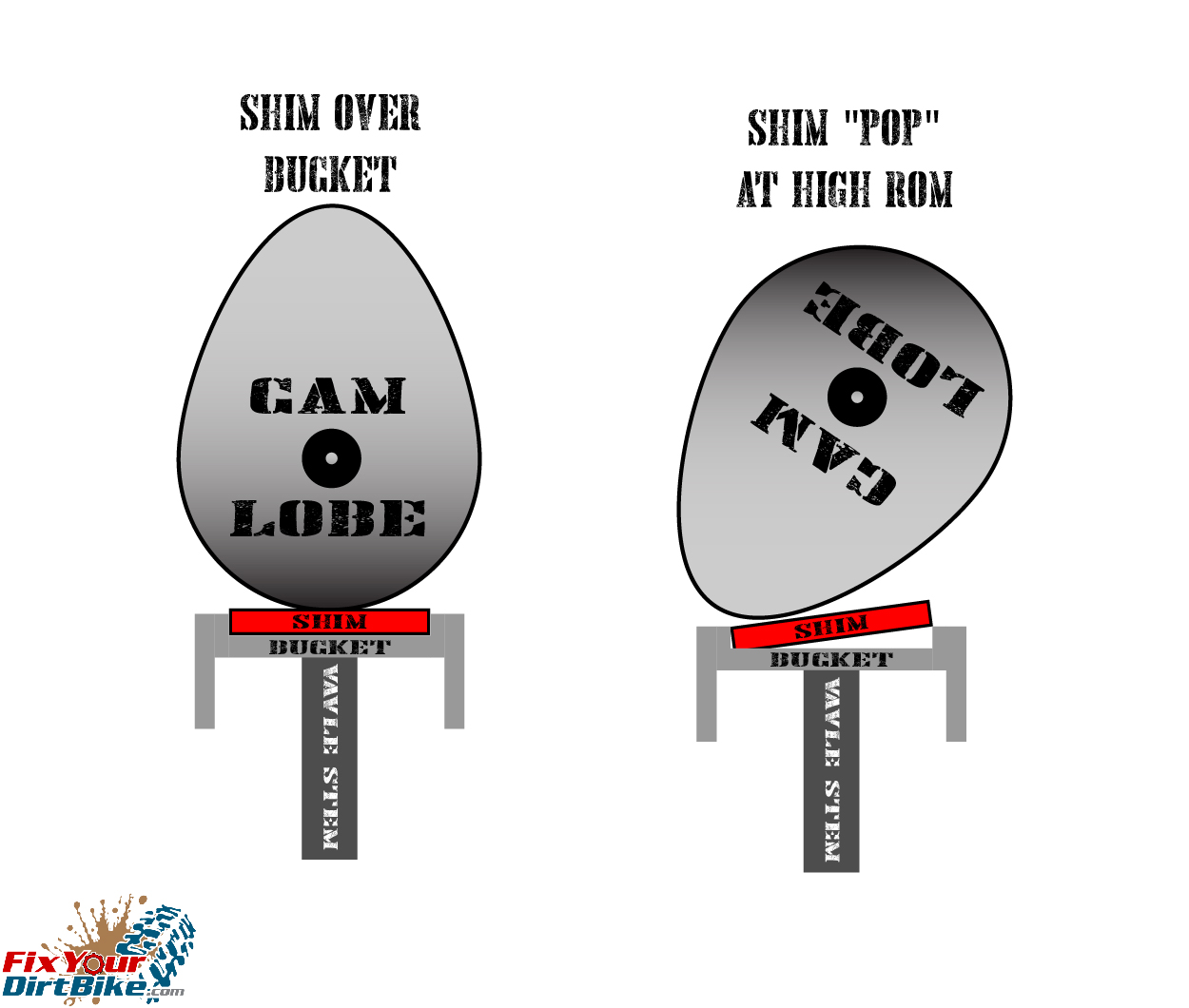
Shim-OVER-Bucket Adjustment
Shim OVER bucket design has a cap at the end of the valve stem referred to as the bucket. On top of the bucket is a shallow recess. A thin piece of metal called a shim sits inside that recess. This thin metal plate can become worn, decreasing valve clearance over time. Shims can’t be adjusted, only replaced to return the valve to correct spec.
As the cylinder head components wear over time, a stock sized shim may no longer be thick enough to maintain stock clearances. Fortunately, different shim thicknesses are readily available to compensate for component wear.
The shim-OVER-bucket setup became the favored style because designers wanted to move away from the use of rocker arms. Instead of actuating valves with rocker arms, the camshaft is in direct contact with the valve bucket. Direct contact reduces valve train mass and frees up potential power. Direct valve contact also increases valve timing precision and longer valve adjustment periods due to the reduction of components that will eventually wear out. As with the valve seat, the shim is a harder material than the bucket, to withstand the constant rub-rub-rub-rub-rub-rub-rub-rub-rub-rub-rub-rub-rub-rub-rub-rub-rub-rub-rub-rub-rub.
The major downside of shim over bucket adjustment is what happens when you get throttle happy and over-rev the engine. We already covered what valve float is, and nothing is keeping that shim in the bucket except the cam. If the spring can’t maintain pressure against the cam lobe, the shim could “pop” and escape the recess in the bucket, and now you have a chunk of metal banging around in the cylinder head. But that’s ok because your bike won’t run anyway.
Shim Over Bucket And High RPM Shim Pop Illustration
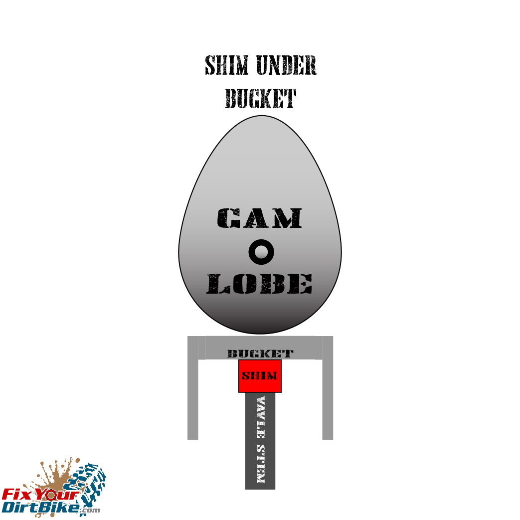
Shim-UNDER-Bucket Adjustment
The next and probably final step was to relocate the shim UNDER the bucket and is the most common modern configuration. Instead of having the shim in contact with the cam lobe, the bucket protects the shim. The cam lobe now contacts the top of the bucket, which, by design, can’t unseat. This change of shim placement allows for even smaller shims to reduce even more weight. I know .01 grams doesn’t sound like much, but it makes a massive difference at 15,000 RPM.
Shim UNDER Bucket Illustration
Motorcycle engineers have spent billions of dollars and thousands upon thousands of hours over the past century to get to this point. Do them a favor, and check your valve clearance!
Fix Your Dirt Bike might use cookies to improve your experience, but you can always opt-out if you want! Cookie settingsACCEPT
Privacy & Cookies Policy
Privacy Overview
This website uses cookies to improve your experience while you navigate through the website. Out of these cookies, the cookies that are categorized as necessary are stored on your browser as they are essential for the working of basic functionalities of the website. We also use third-party cookies that help us analyze and understand how you use this website. These cookies will be stored in your browser only with your consent. You also have the option to opt-out of these cookies. But opting out of some of these cookies may have an effect on your browsing experience.
Necessary cookies are absolutely essential for the website to function properly. This category only includes cookies that ensures basic functionalities and security features of the website. These cookies do not store any personal information.
Any cookies that may not be particularly necessary for the website to function and is used specifically to collect user personal data via analytics, ads, other embedded contents are termed as non-necessary cookies. It is mandatory to procure user consent prior to running these cookies on your website.

 The front master cylinder design on your Yamaha YZ125 had some slight redesigns between 1994 and 2001, but the same service applies to all model years.
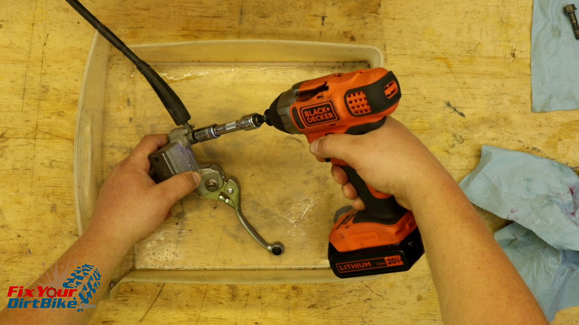


 The rear caliper design on your Yamaha YZ125 had some slight redesigns between 1994 and 2001, but the same service applies to all model years.
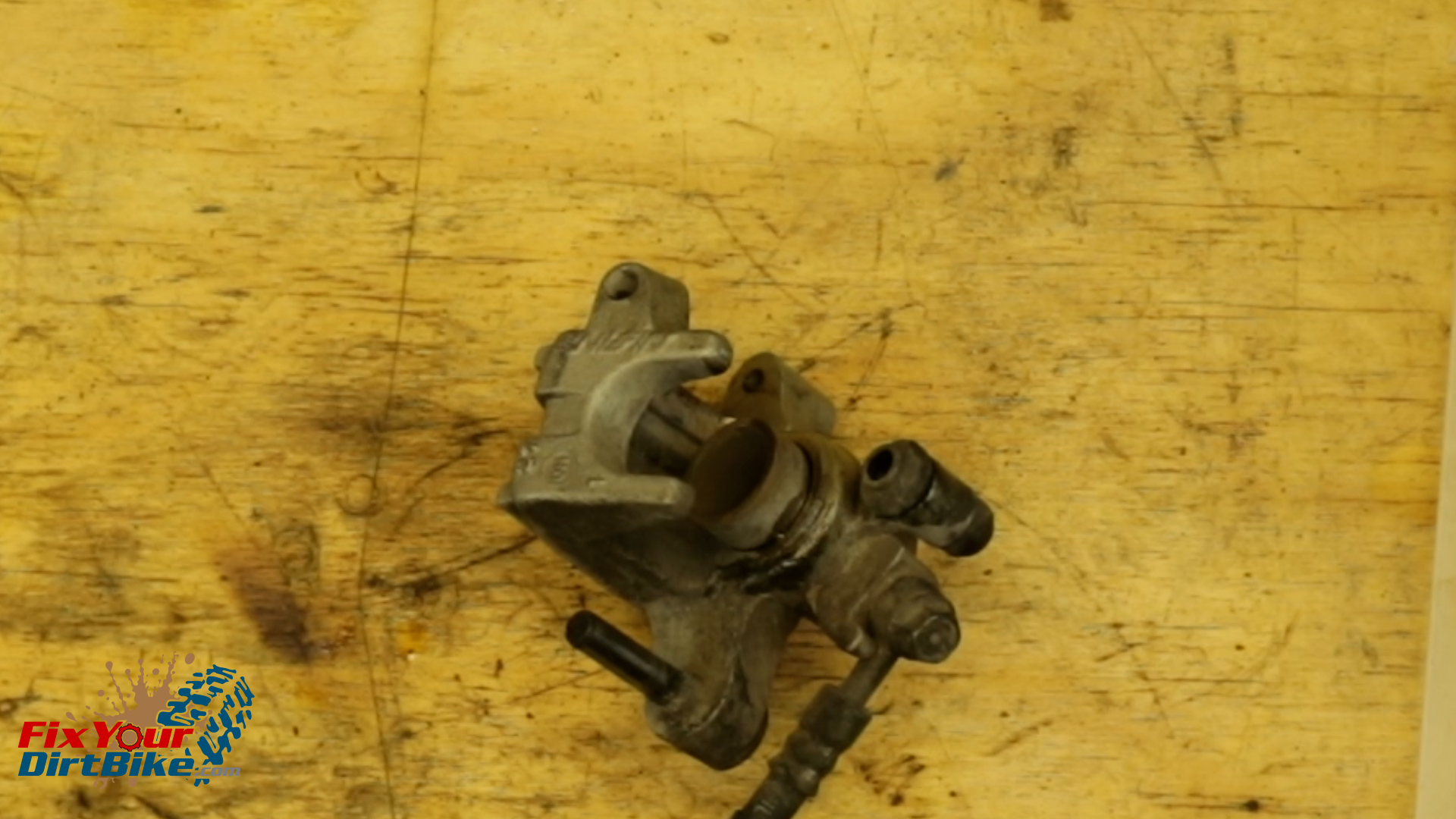

 The front caliper design on your Yamaha YZ125 had some slight redesigns between 1994 and 2001, but the same service applies to all model years.
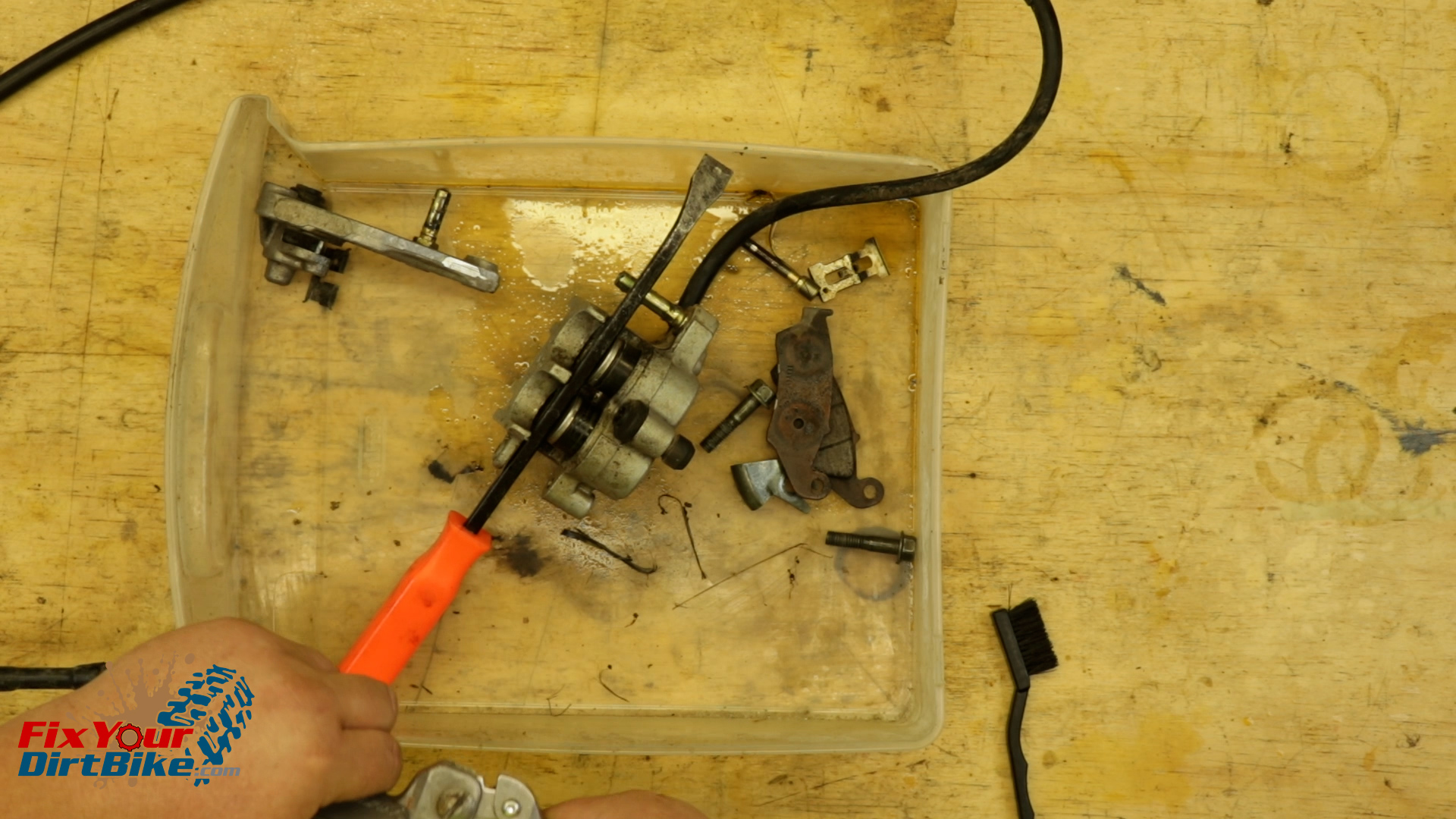

 Over the years, motorcycle builders have come up with multiple methods of keeping valves within adjustment for as long as possible before needing to adjust lash.