How To Troubleshoot & Test The Ignition System On Your 1994-2001 Yamaha YZ125

Electrical troubleshooting can get very frustrating, and it’s very easy to lose track of what you’ve done and still need to do, so write down everything you need to test, then as you go, write down the test results.
You want to start with the simplest solution; there’s no sense replacing the stator when all you had was a ground fault.
So start with the spark plug, then work your way back to the stator.
You can only test the CDI through the process of elimination, so if everything else is tested within spec, the CDI will need to be replaced.
For whatever reason, Yamaha does not provide peak voltage specs for anything, so If you want to do a physical test of your ignition coil, you will need to take it to a shop and have it tested.
Here’s a link to open the YZ125 Electrical System Specifications in a new window.
My Yz125 has spark, but it’s very weak. My bike will start idle and rev just fine, but as soon as it’s under load, it chokes out. When I pull the plug, its wet, not damp, but wet with oil. I know it’s not a carb issue, but I’ll get into that in the carb video.
After working through this troubleshooting procedure, I found that the resistance of the primary winding of my ignition coil was metering way out of spec.
You will need a multimeter if you get to the ignition coil and stator. If you don’t have a multimeter yet, you can get one HERE.
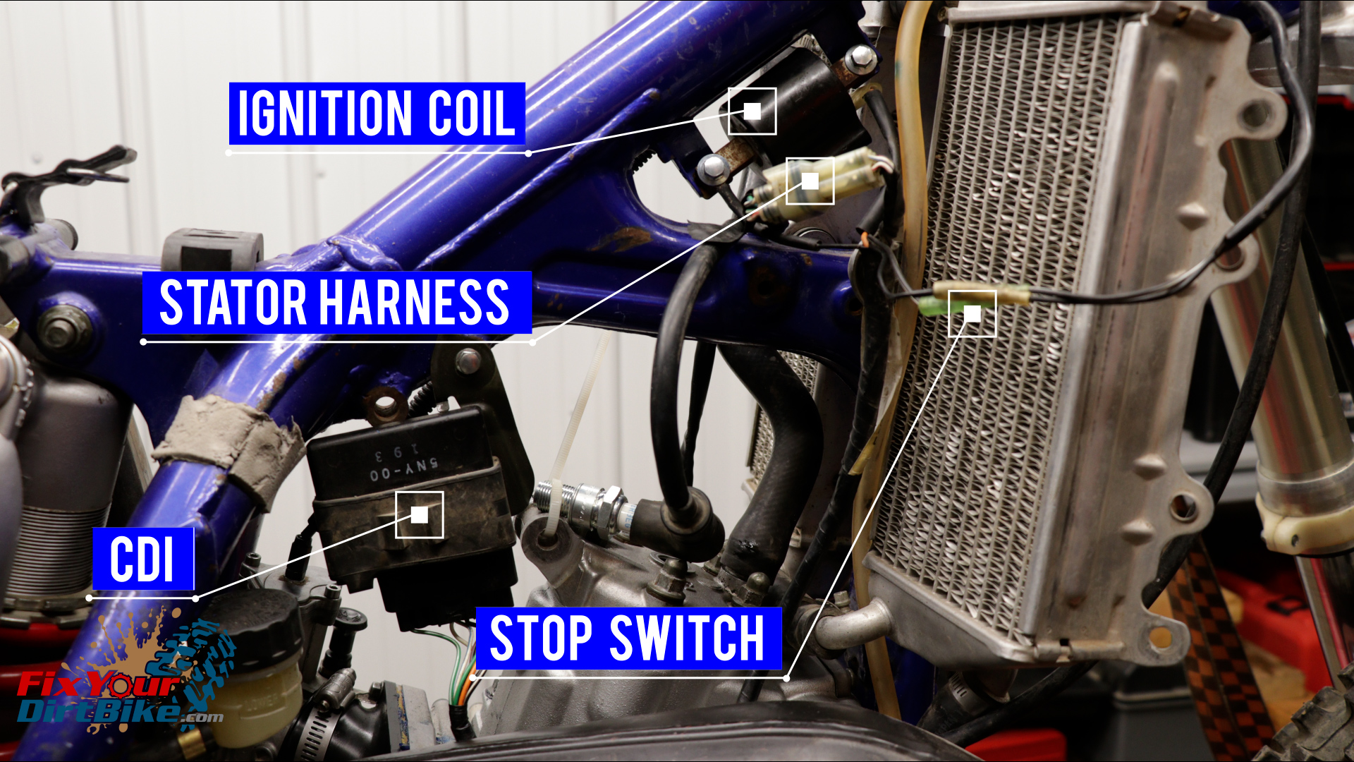
Ignition Troubleshooting Prep
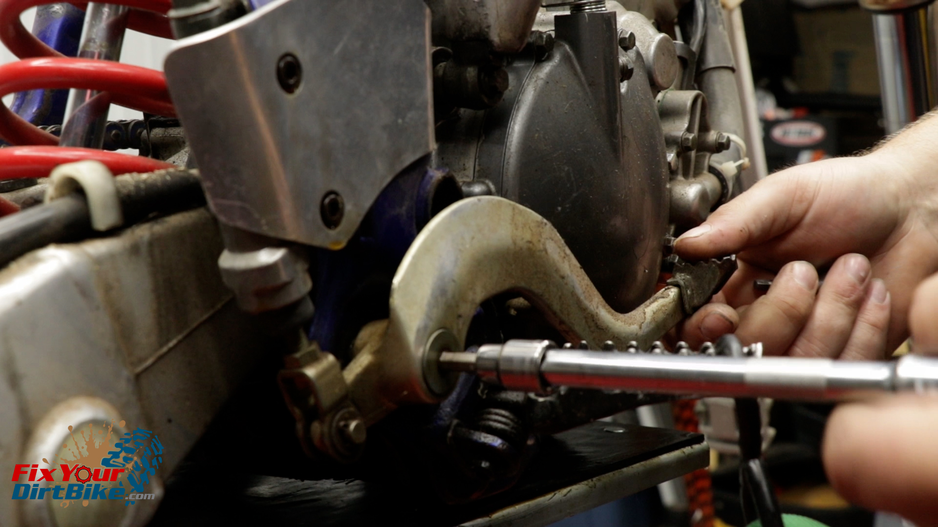
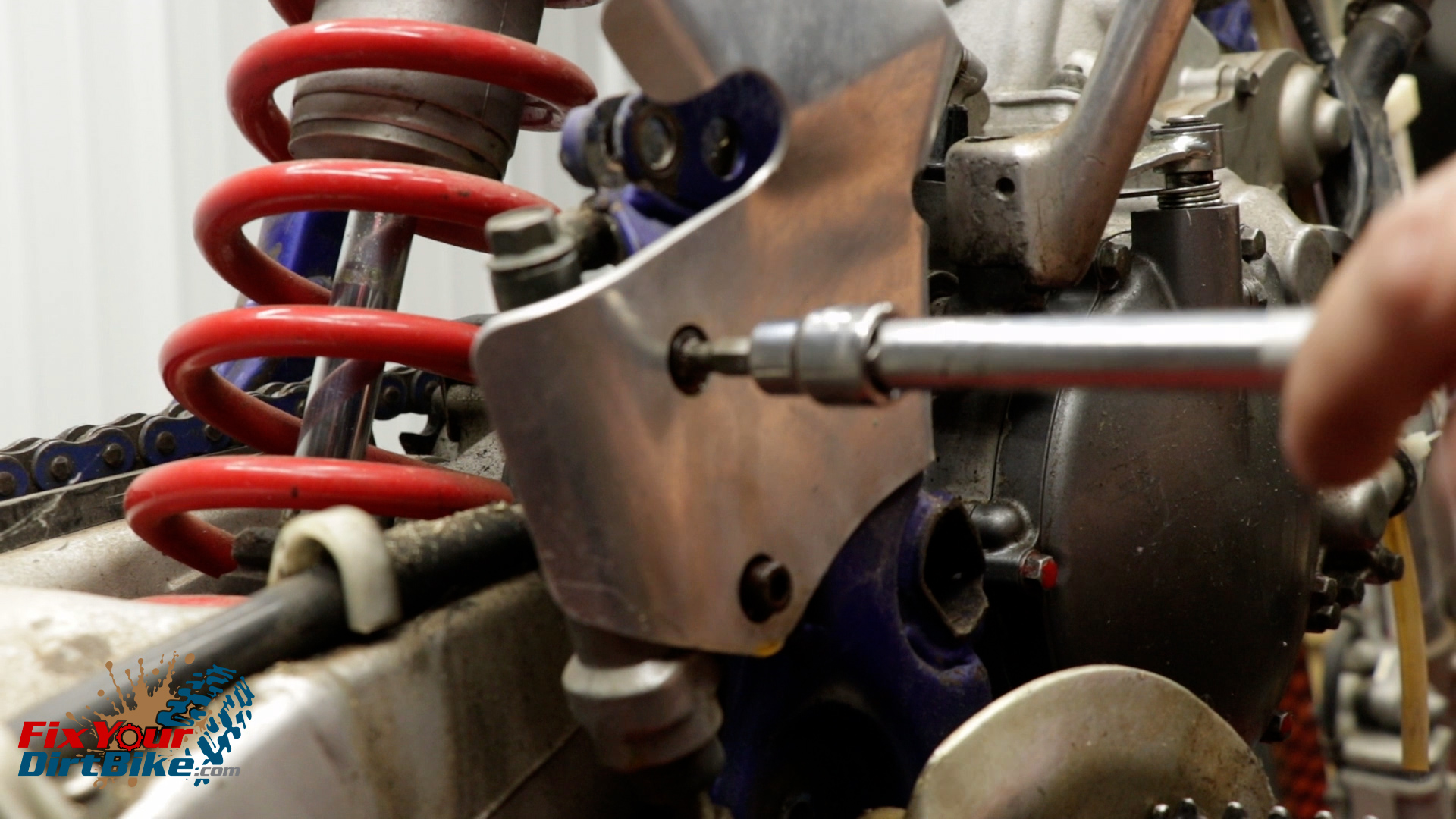
- Pull your seat, plastics, and gas tank to gain access to the electrical components.
- You can access everything from the right side of your bike.
- You can’t test the CDI, so leave it alone.
- Make sure everything is securely connected, and every contact point is clean.
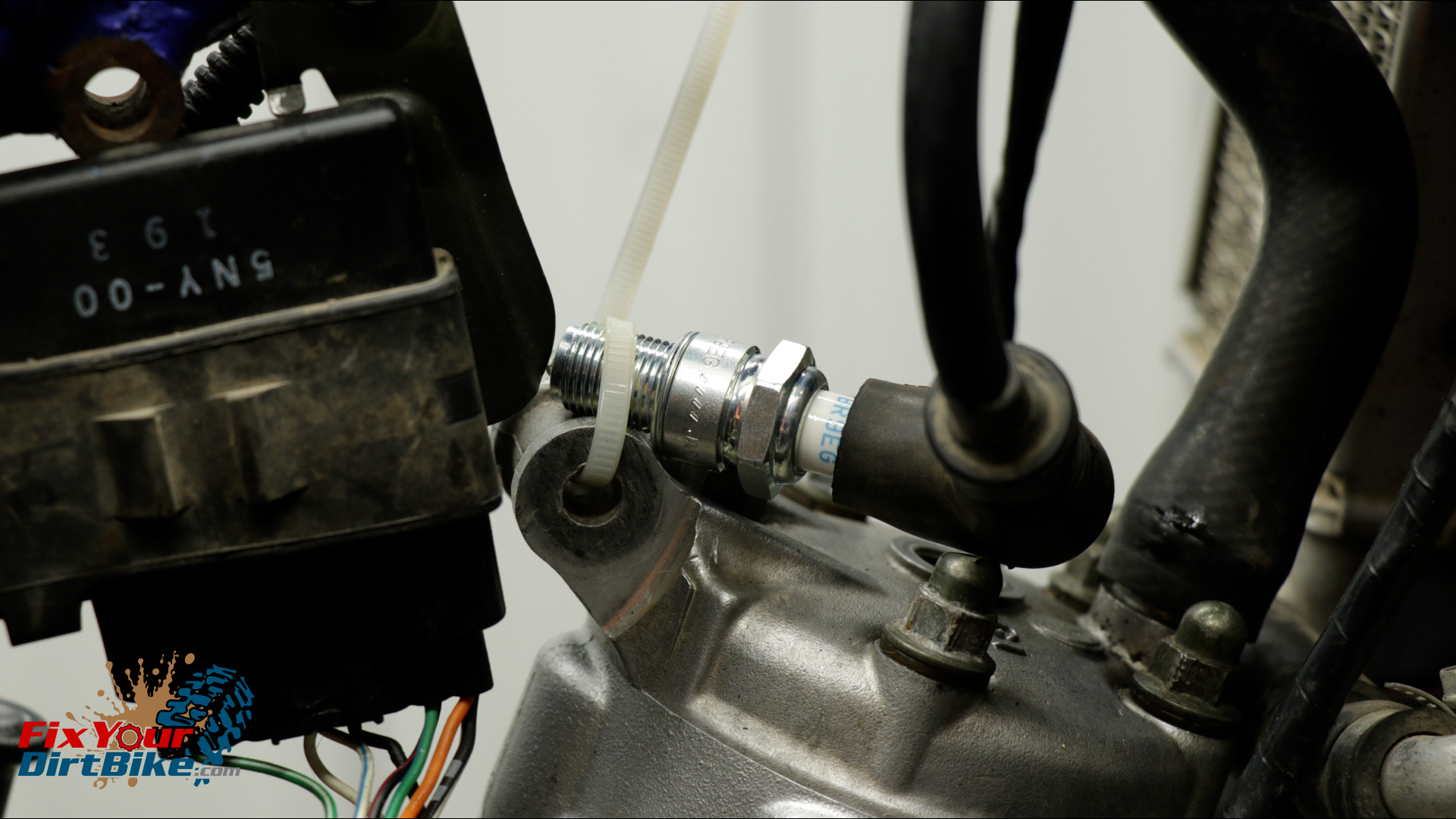
- Remove your spark plug and zip tie it to the cylinder.
- If you continuously kick the engine over without grounding the plug, you will overload and burn out the ignition coil.
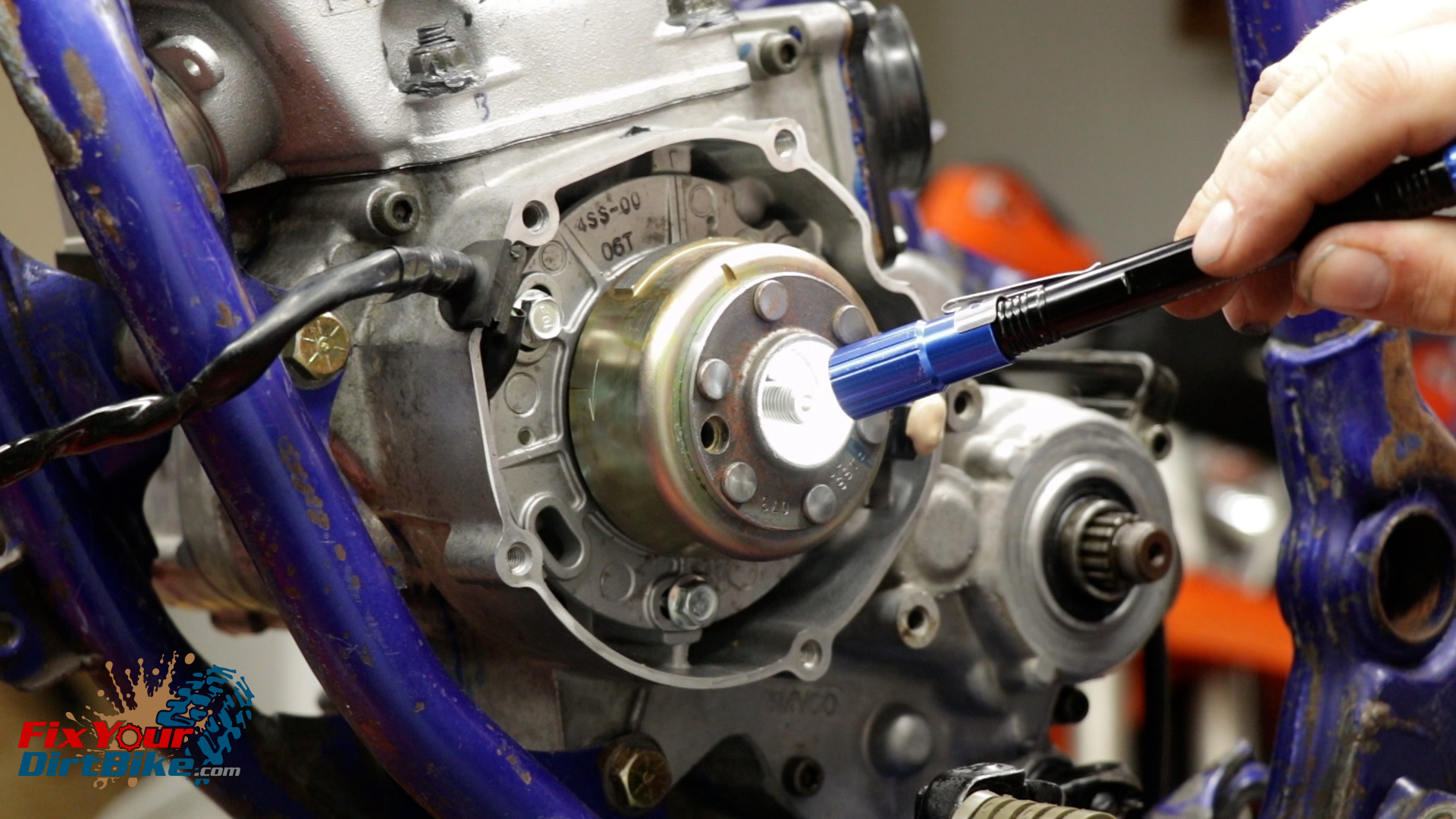
- Check that your flywheel is installed properly on the woodruff key, and the stator timing mark is aligned with the arrow on the case.
- Most importantly, start testing with a NEW spark plug gapped between 0.019 to 0.024 inches, and make sure your NEW plug is seated firmly in the plug boot.
Step 1: Ground Fault
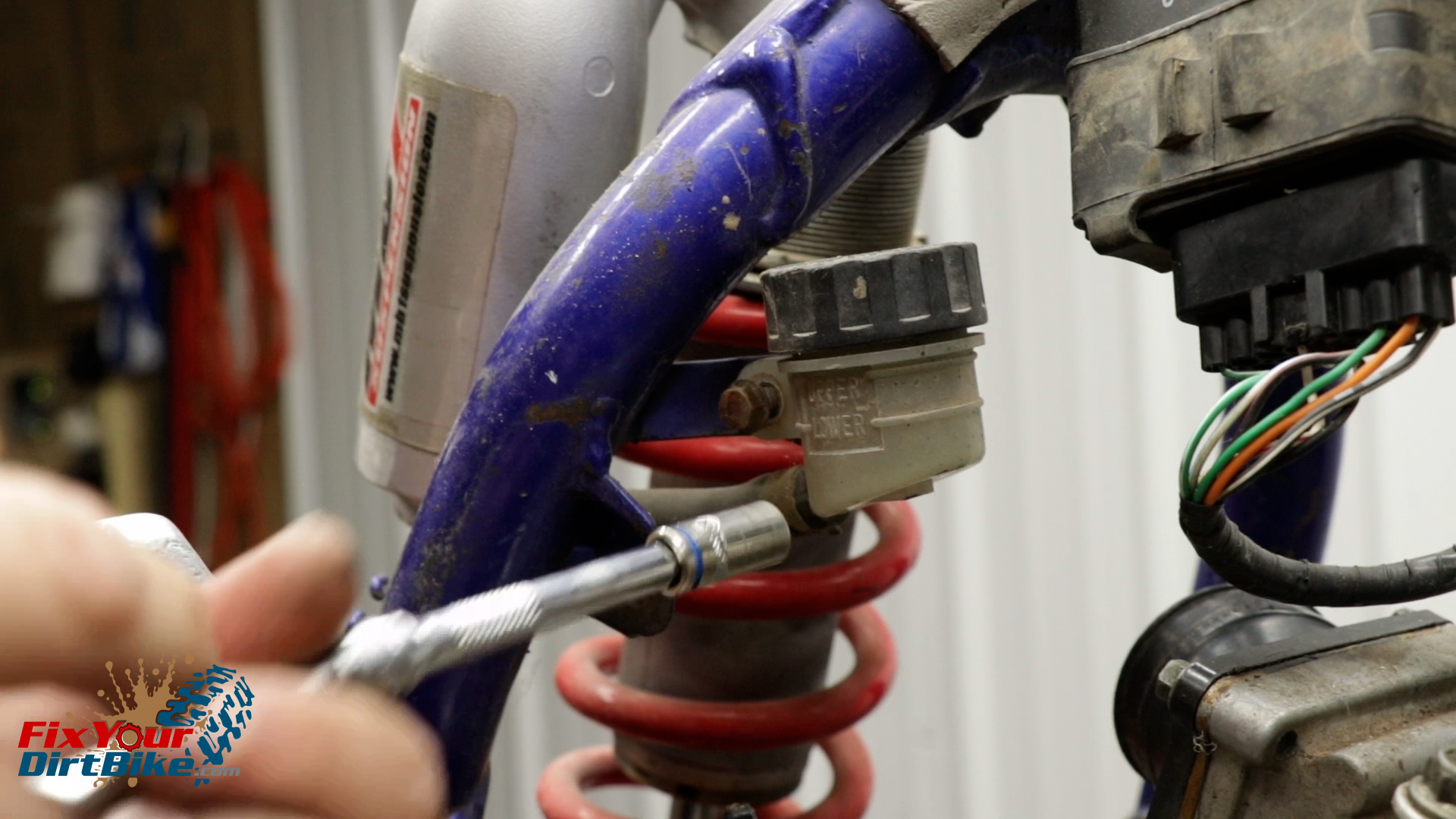
- Start by looking for pinched wires or jackets that have been worn through.
- You may want to unwrap the main loom from the stator to be safe.
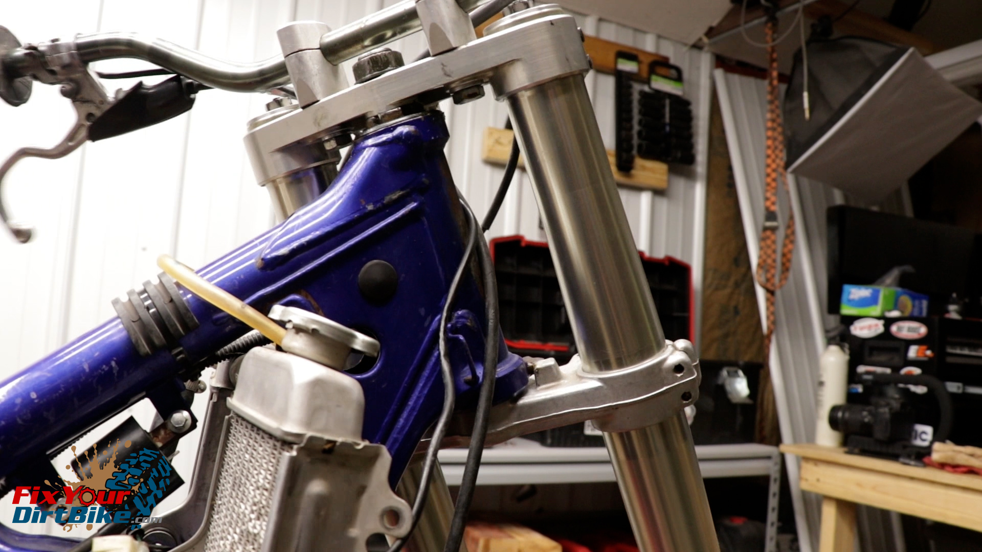
- A common pinch point is the engine stop switch wires getting pinched at the steering stem.
- If the wires look good, test the switch itself.
- The engine stop switch works by shorting the ignition system to ground, so if it has continuity without pressing the switch, it needs to be replaced.
- The simplest way to test your stop switch is to disconnect the leads and kick your bike over.
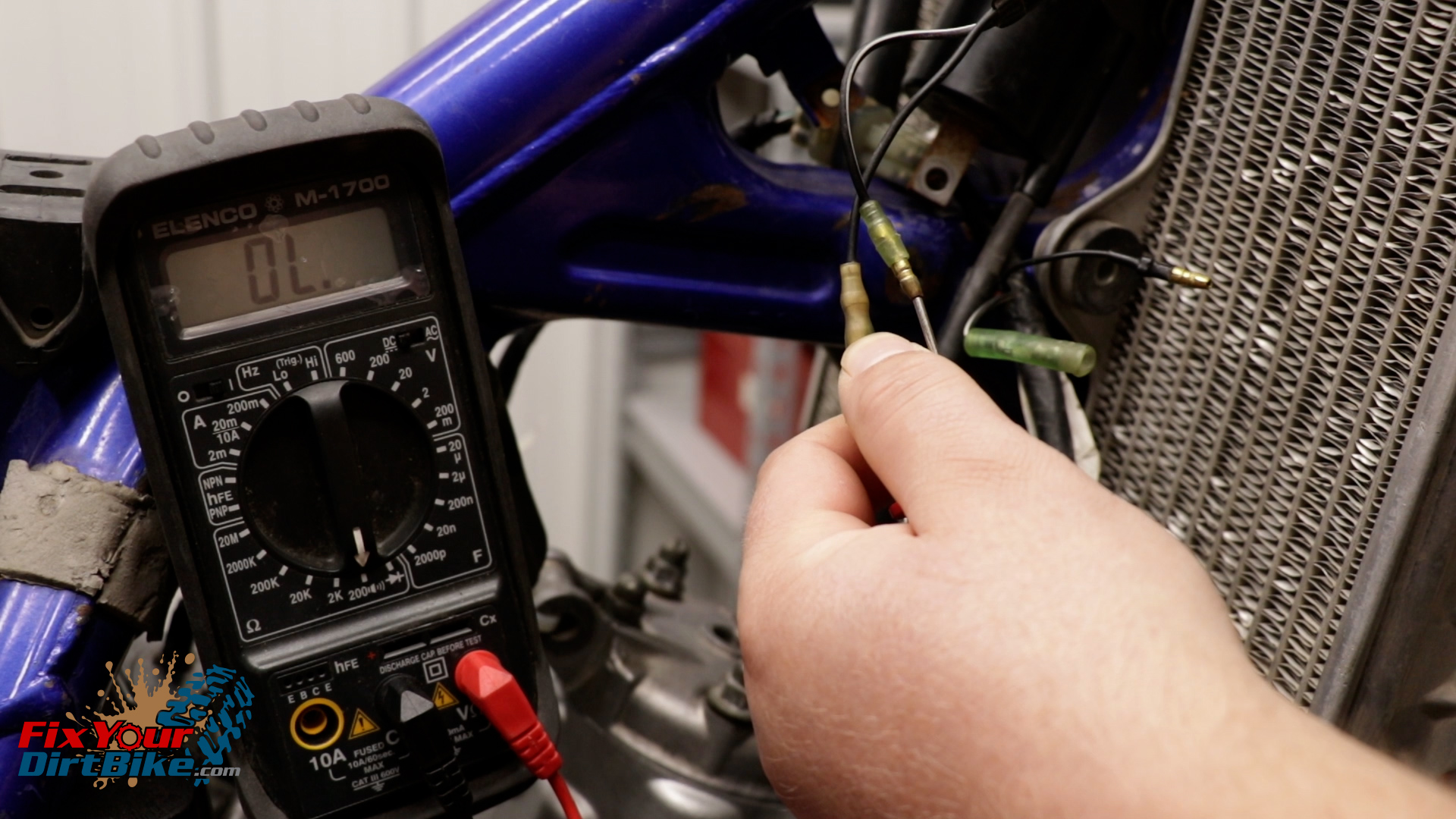
- You can also meter the engine stop switch for continuity.
- Connect your multimeter leads to the switch wires, and you should only see continuity with the button pressed.

Step 2: Spark Testing
- With the spark plug secured to the cylinder, which you made sure to do before you started… kick your bike over.
- You should see a strong blue spark.
- My spark was blue, but it was very weak.
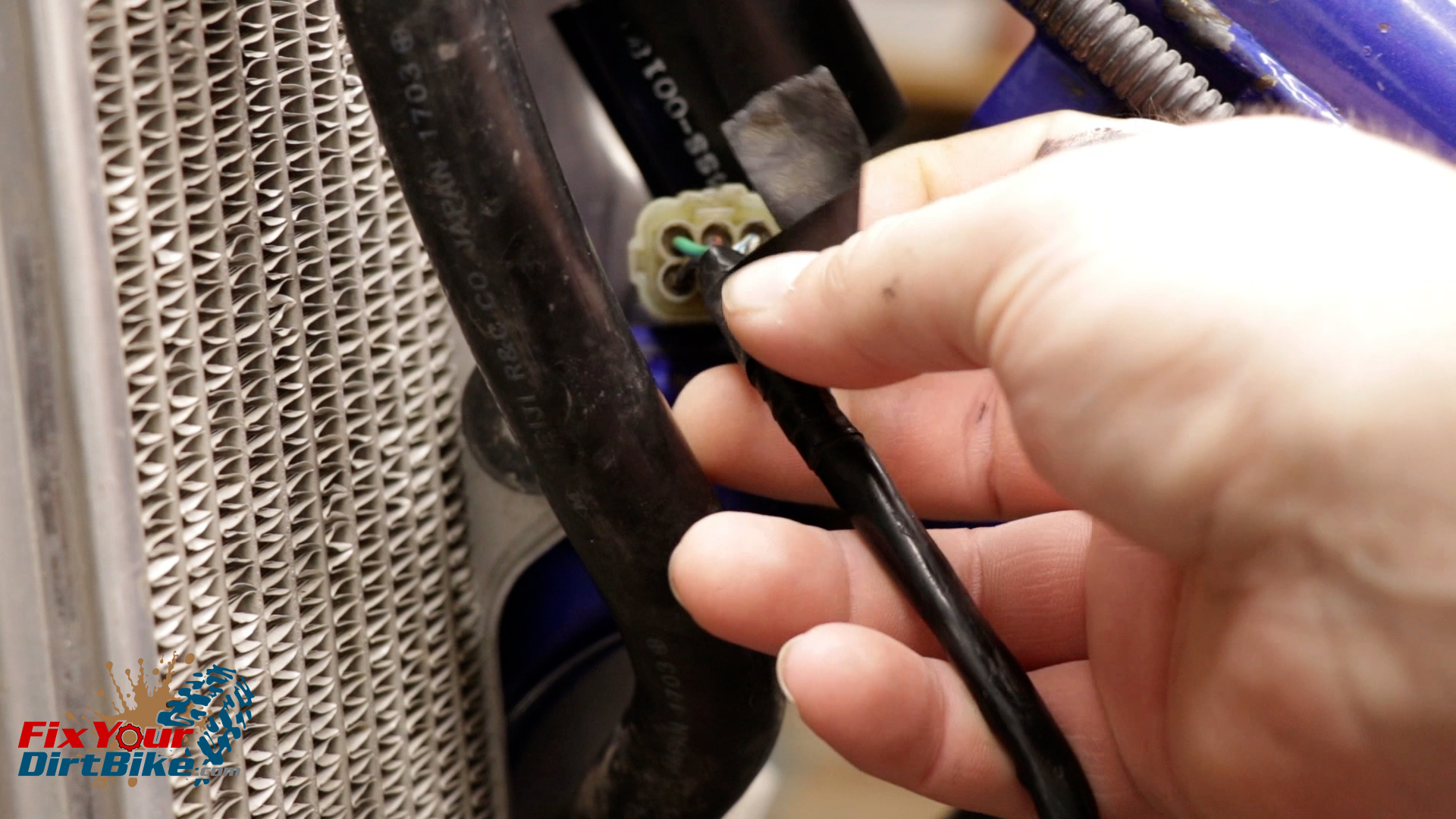
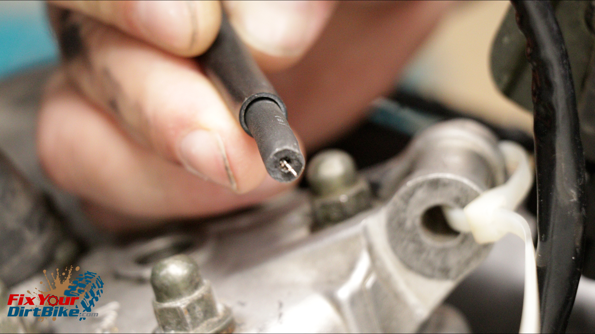
- Next, unscrew the spark plug boot from the wire.
- Make sure you can see the core wires inside the jacket.
- If you can’t, start cutting the jacket back a ¼ inch at a time until you see wires, re-attach the plug boot, and test again.
- If your plug boot and wire connection are solid, but still no spark, remove the boot and keep testing.
- Hold the unterminated lead about a 1/8th of an inch away from your cylinder, and kick your bike over.
- You should see a strong blue spark.
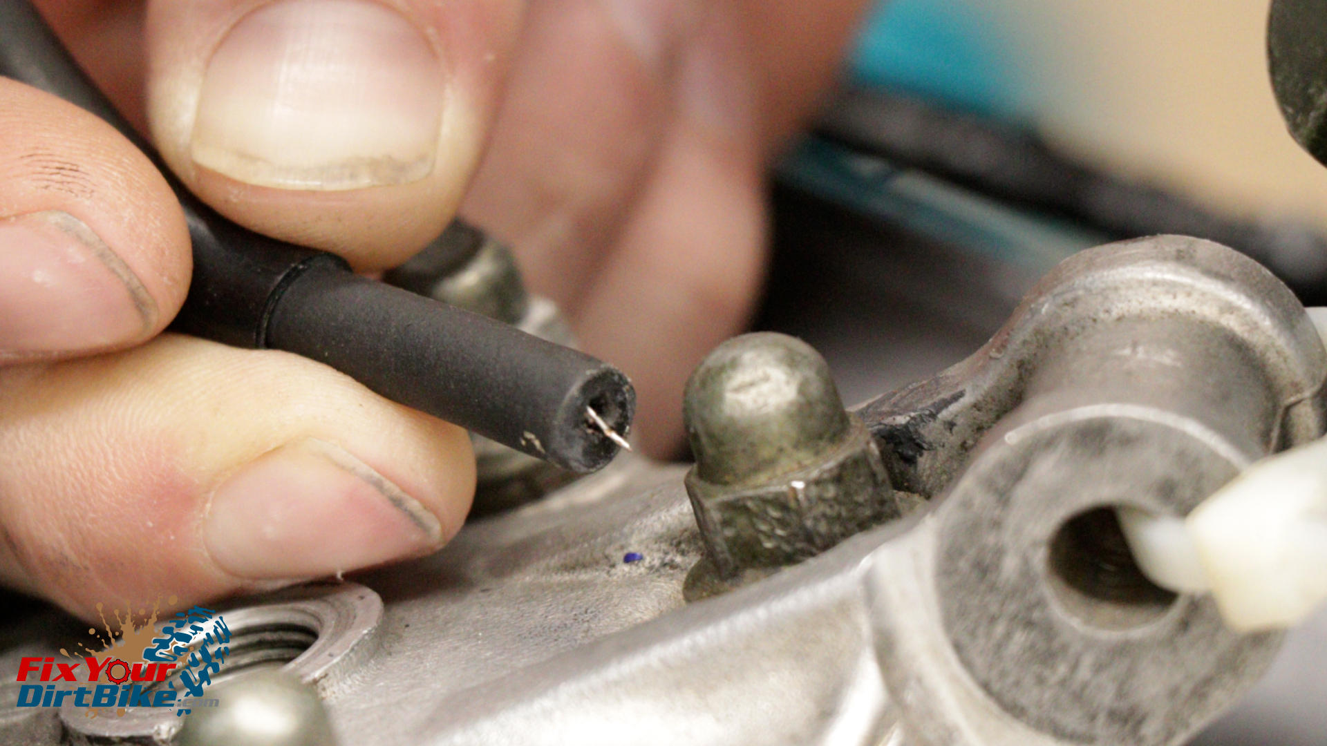

Spark Test Results
- If you get a strong spark with the unterminated wire, and not with the spark plug and boot, replace the boot.
- If the spark is strong with the unterminated wire but weak with the spark plug and boot, replace the boot.
- If the spark is weak with the unterminated wire, your ignition coil is suspect and needs further testing.
Step 3: Component Testing
Ignition Coil
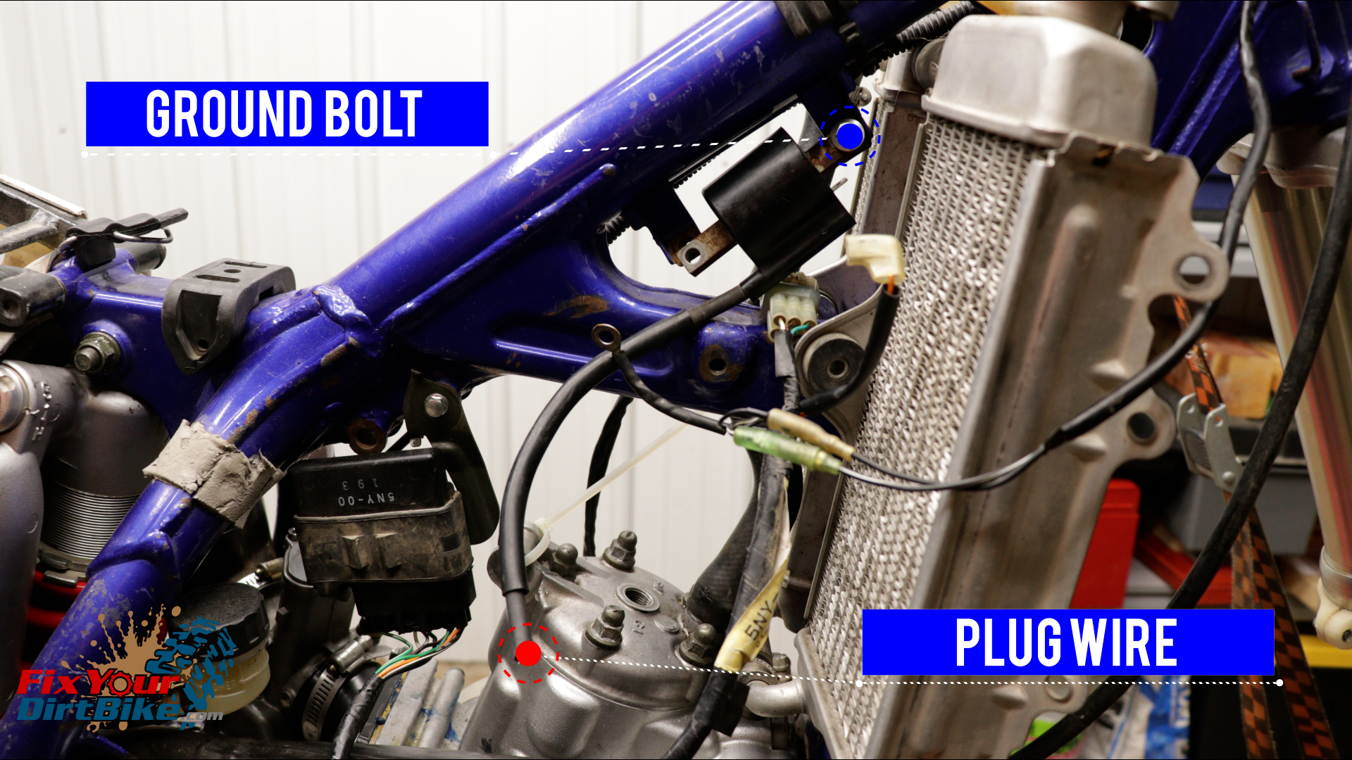
- Unplug the CDI from the ignition coil, and remove the ground wire.
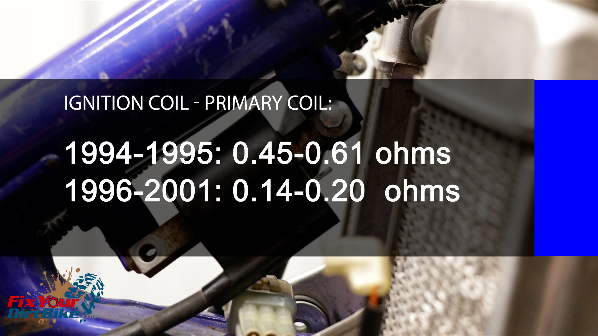
- Meter the primary and secondary winding resistance of the Ignition coil.
- The primary coil is metered between the CDI connection and the mounting flange on the same end.
- 1994-1995 models should meter between 0.45-0.61 ohms
- 1996-2001 models should meter between 0.14-0.20 ohms
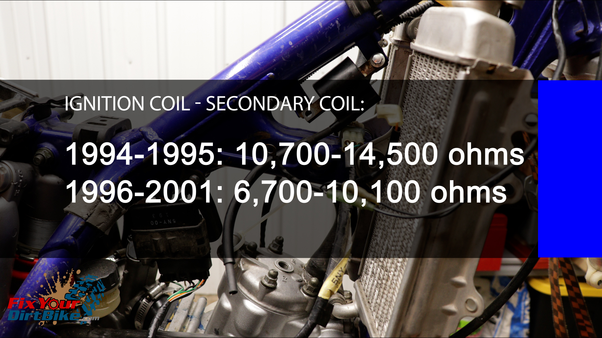
- The secondary winding is metered between the same mounting flange as the primary winding and the unterminated spark plug wire.
- 1994-1995 models should meter between 10,700-14,500 ohms
- 1996-2001 models should meter between 6,700-10,100 ohms

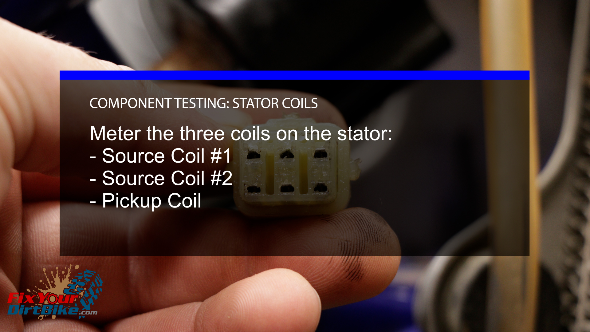
Stator Coils
- Meter the three coils on the stator; Source Coil #1, source coil #2, and the pickup coil.
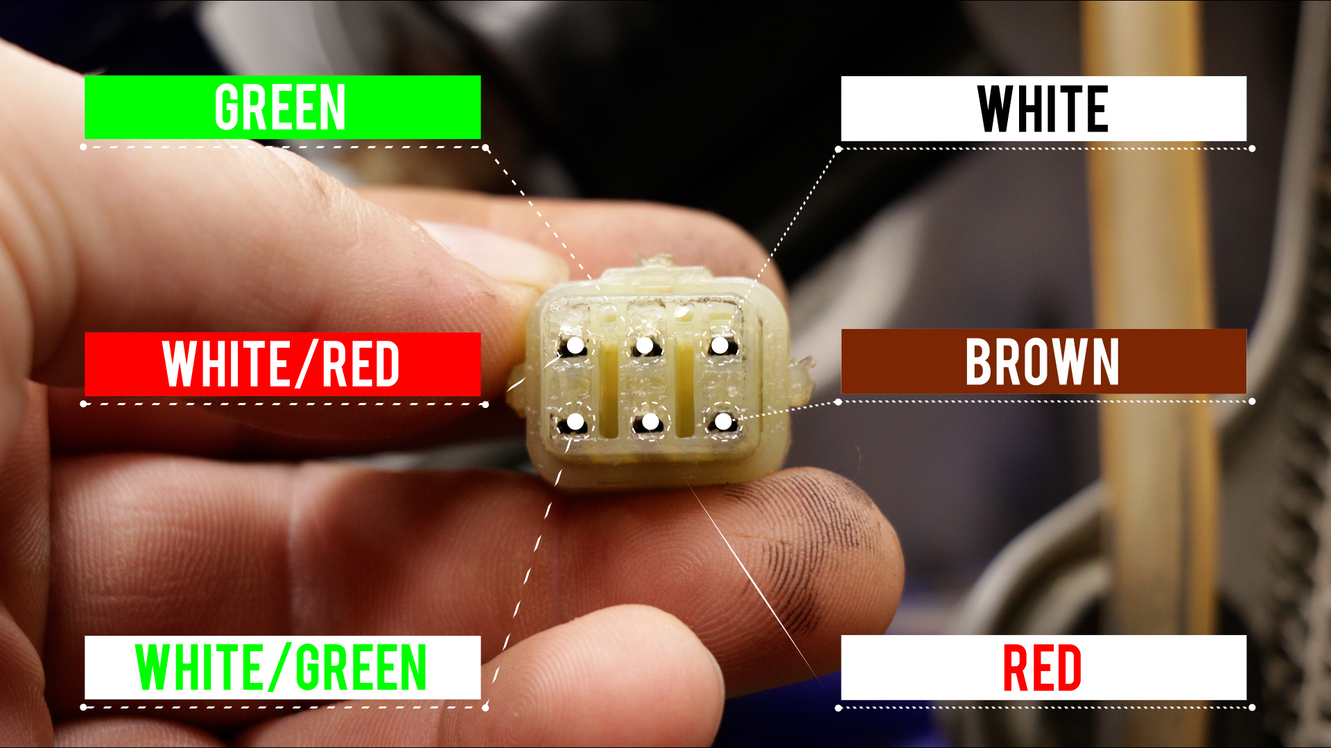
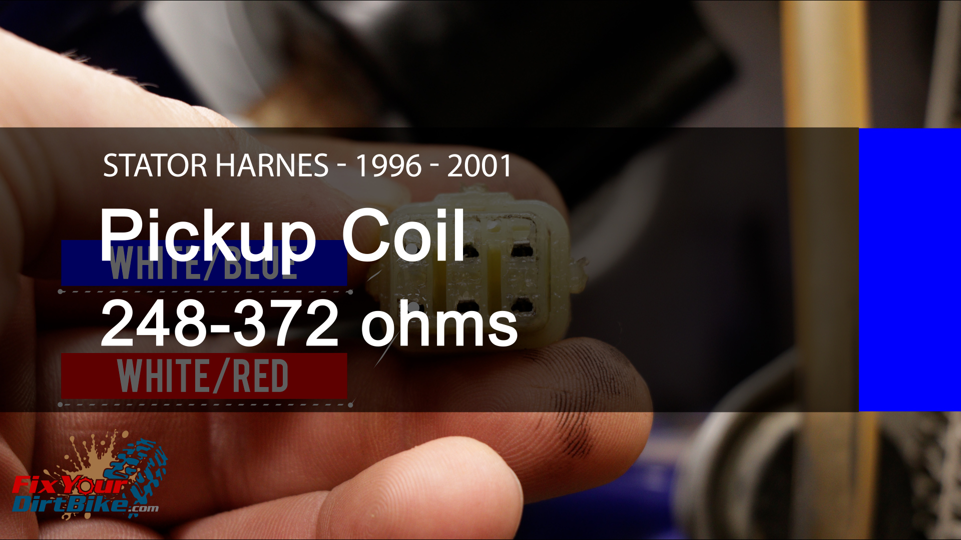
- The wiring changed from 1995 to the 1996 model year; both models use the same six-pin harness, but with different colored wires.
- My bike is a 2001 model, so I will start with the 94-95 model and then demonstrate testing with the 96-01 model.
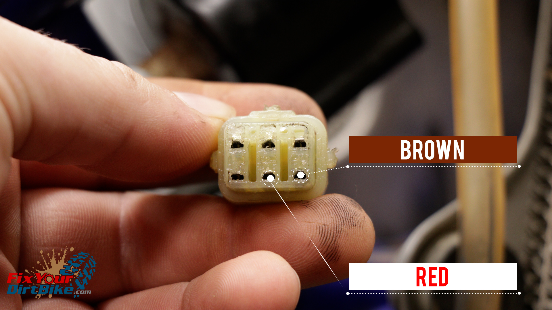
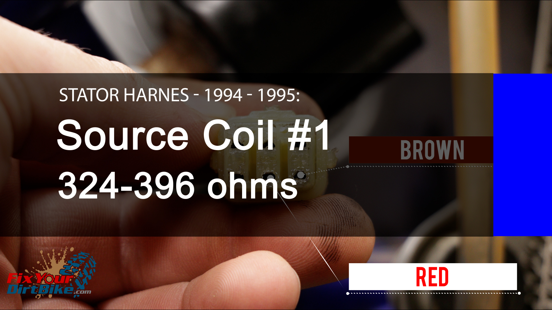
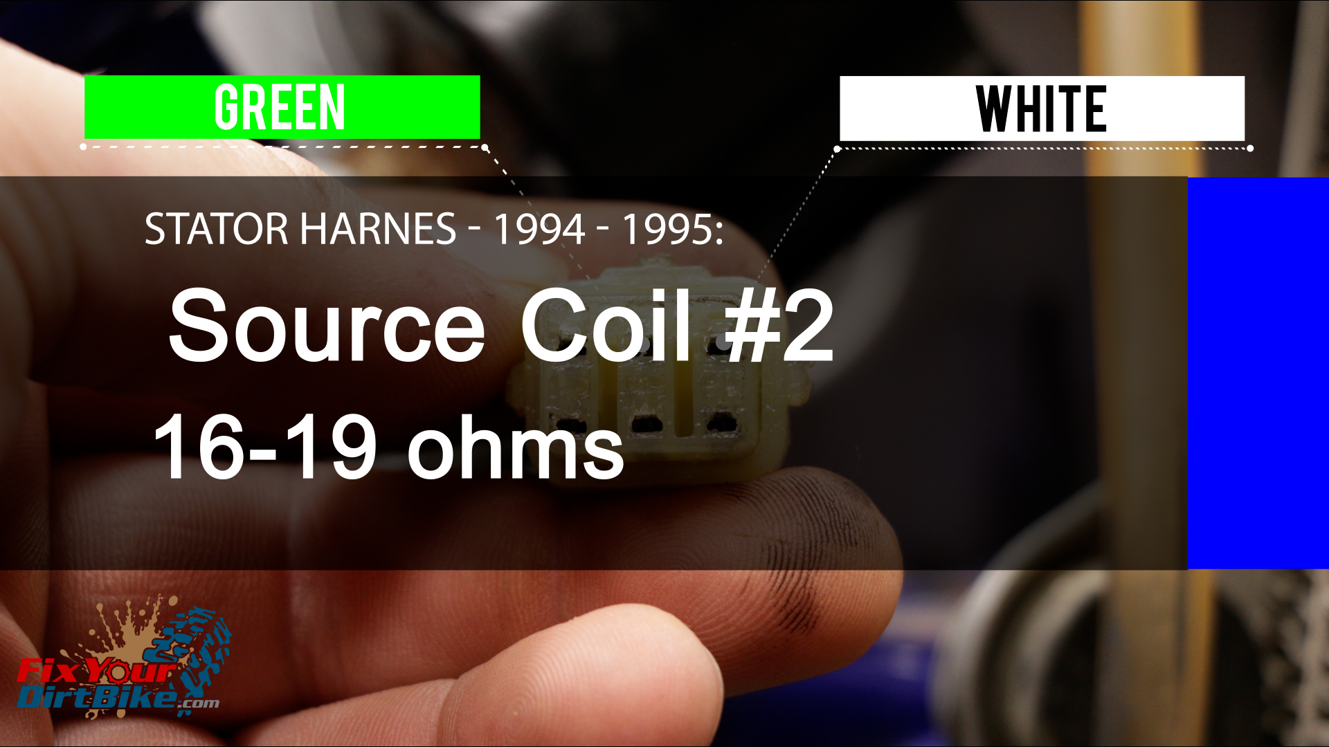
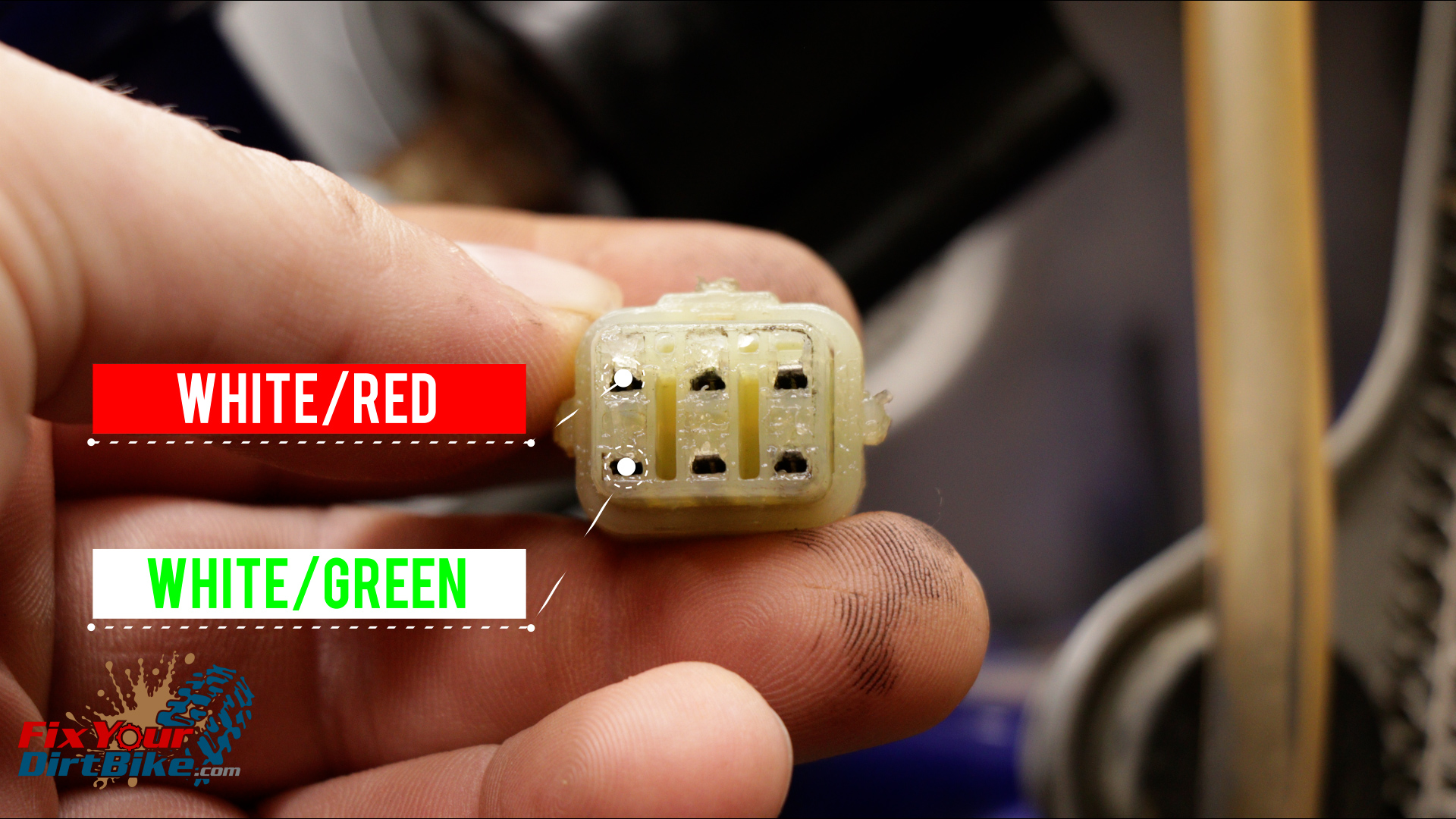
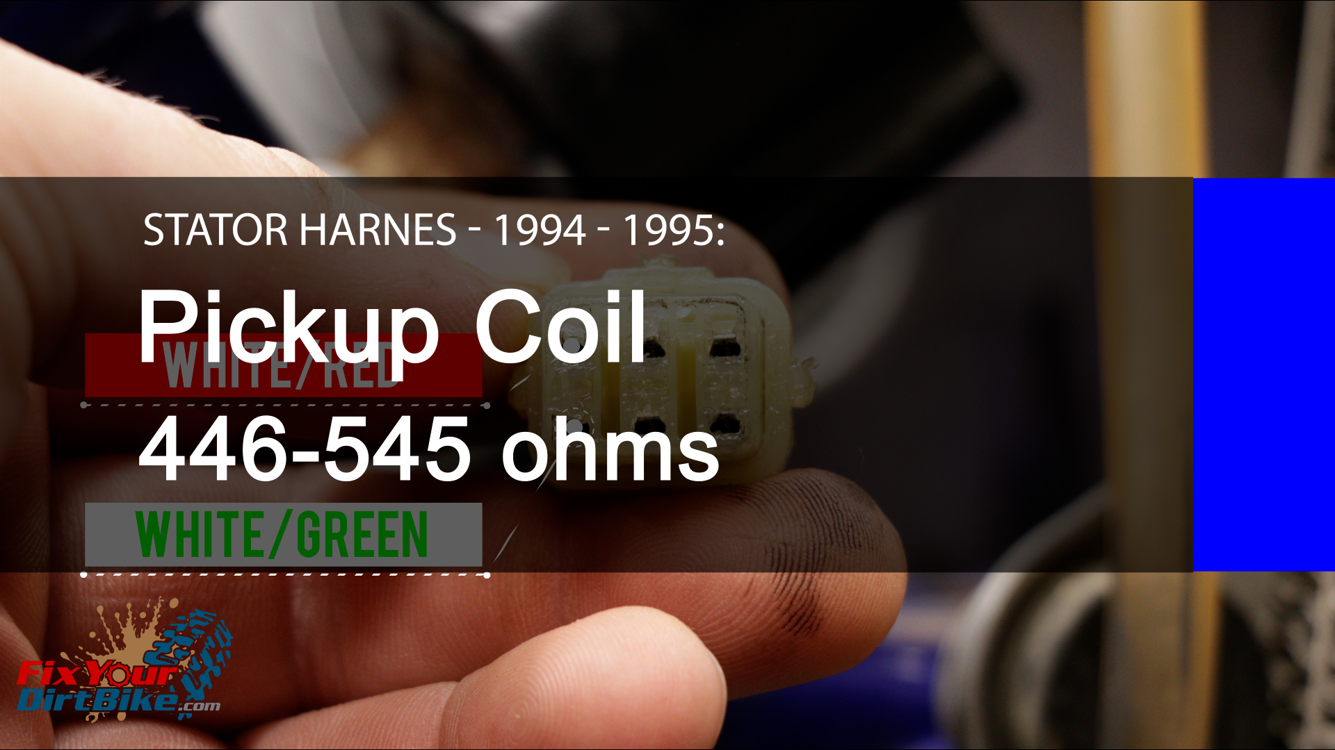
1994-1995
- Measure source coil #1 between the Brown and Red wires; the resistance should measure between 324 and 396 ohms.
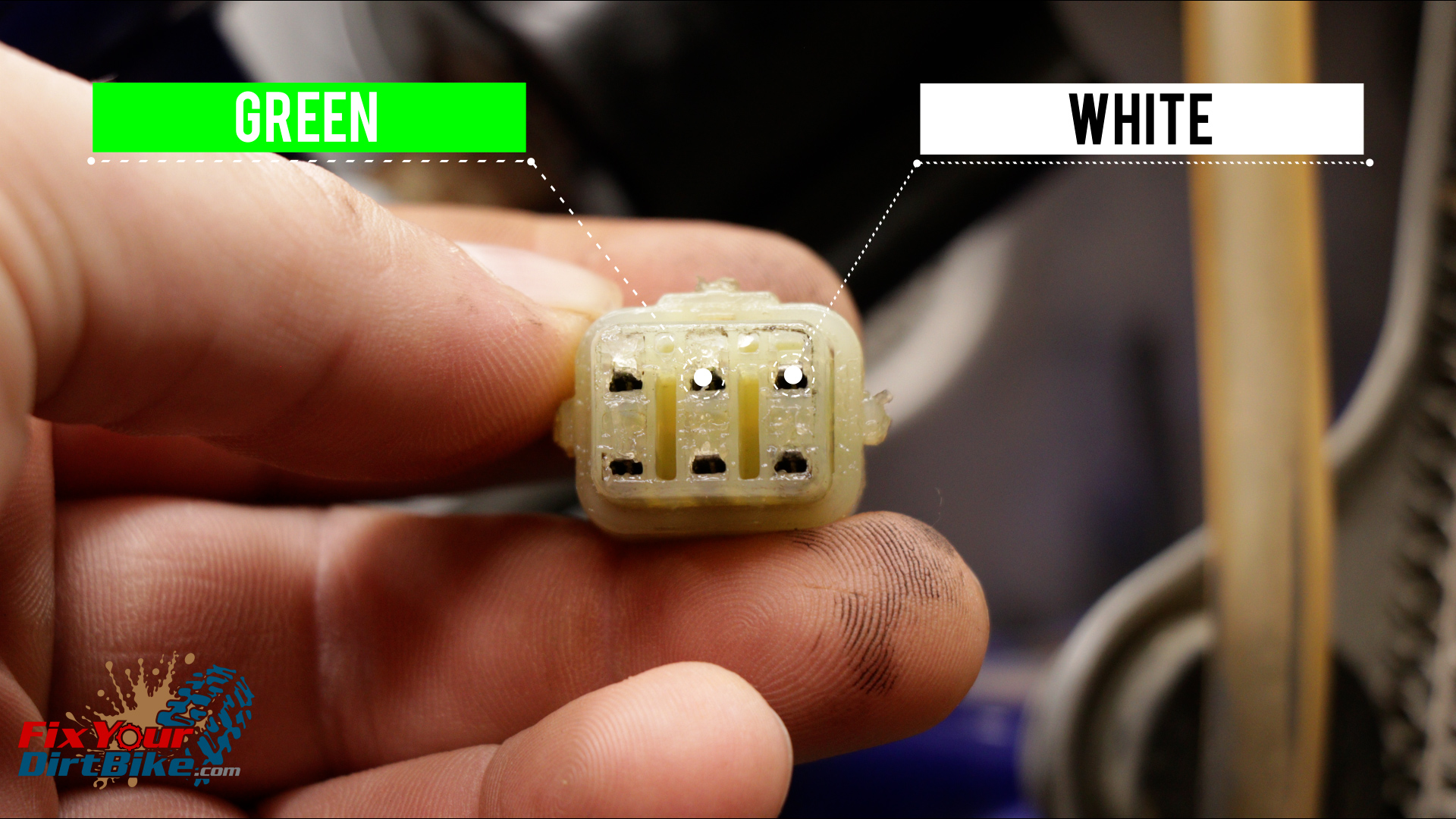
- Measure source coil #2 between the White and Green wires; the resistance should measure between 16 and 19 ohms.
- Measure the Pickup Coil between the White/Green and White/Red wires; the resistance should measure between 446 and 545 ohms.
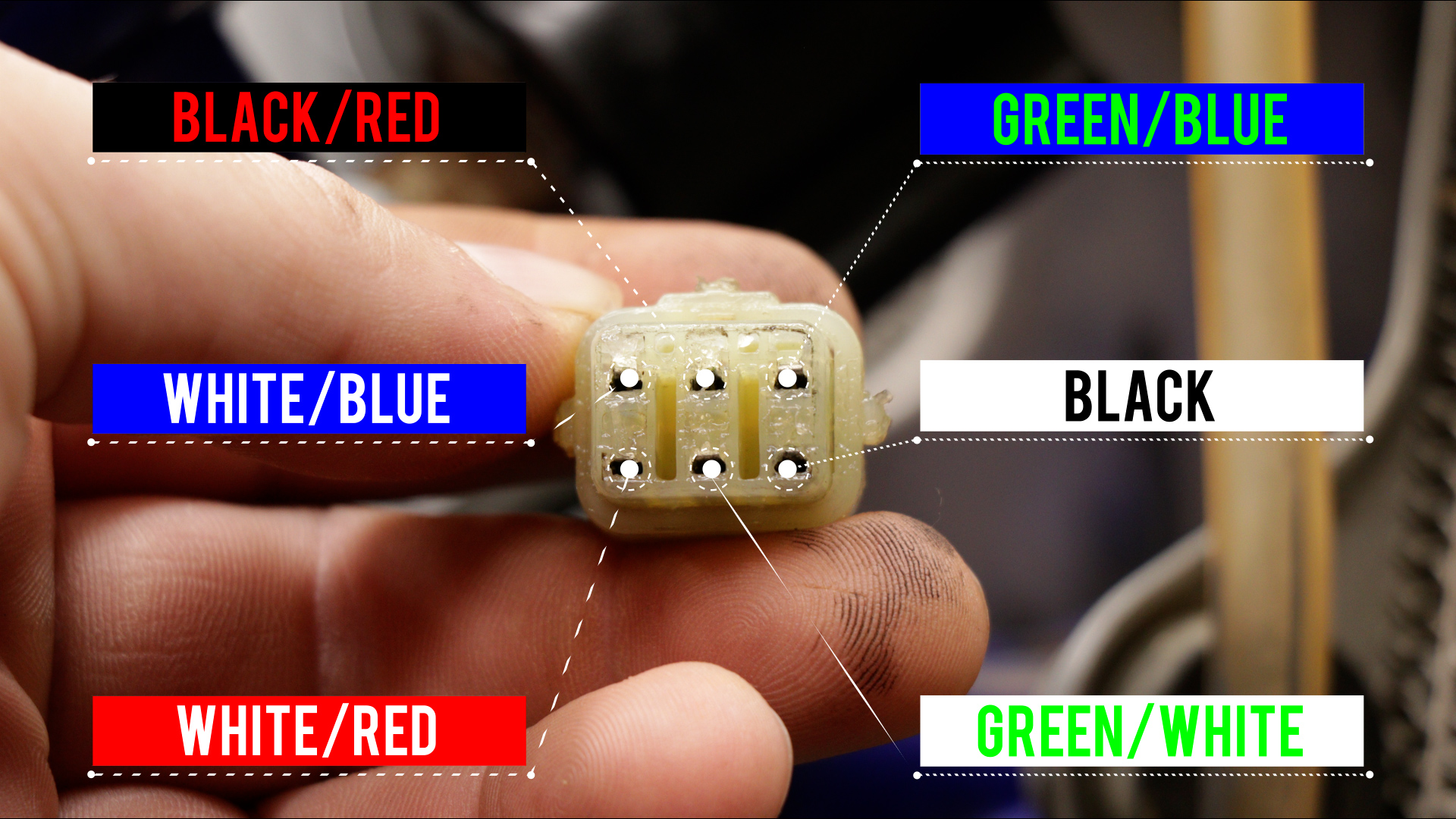
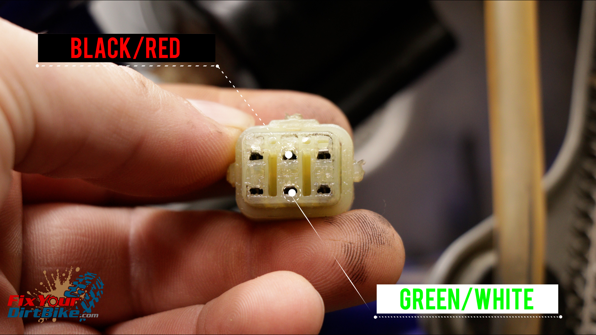
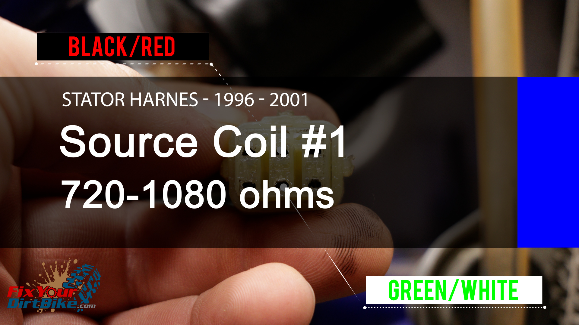
1996-2001
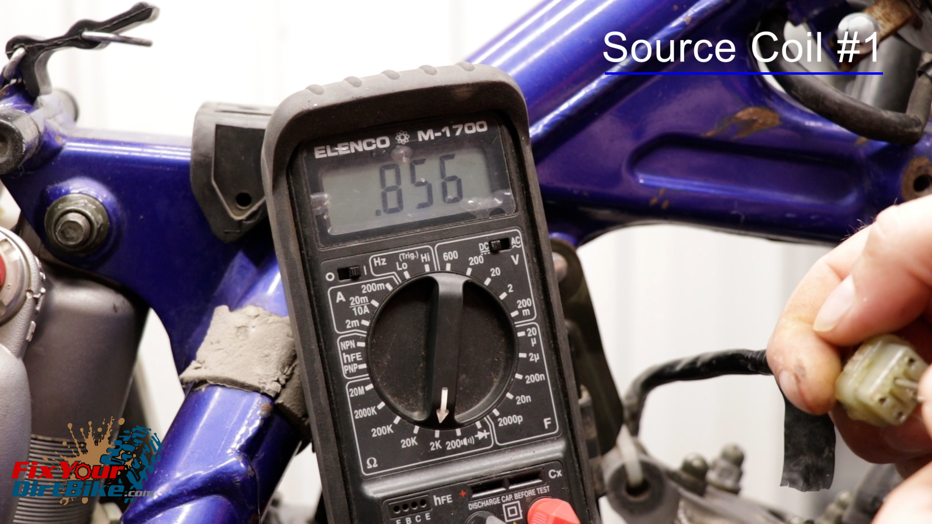
- Measure source coil #1 between the Green/White and Black/Red wires.
- The resistance should measure between 720 to 1080 ohms.
- My #1 coil metered at 856 ohms.
- The resistance should measure between 720 to 1080 ohms.
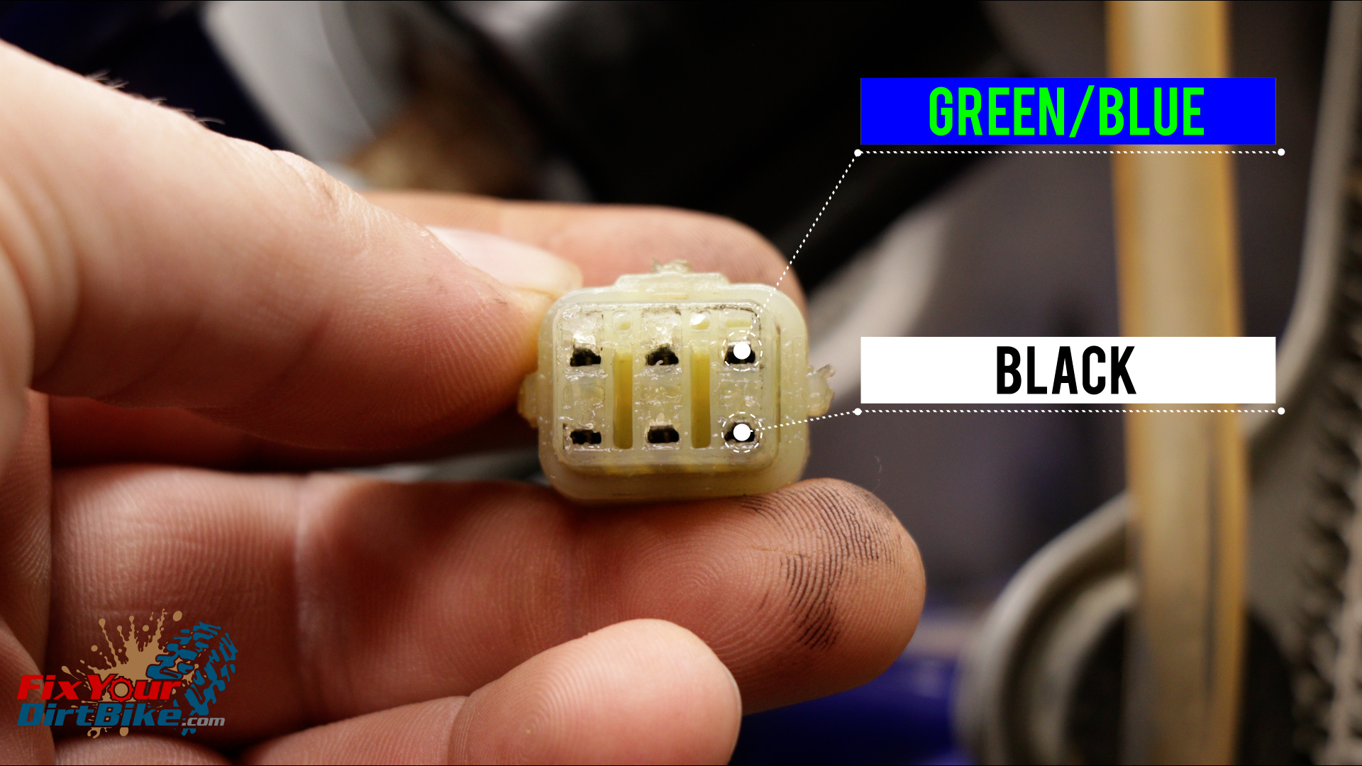
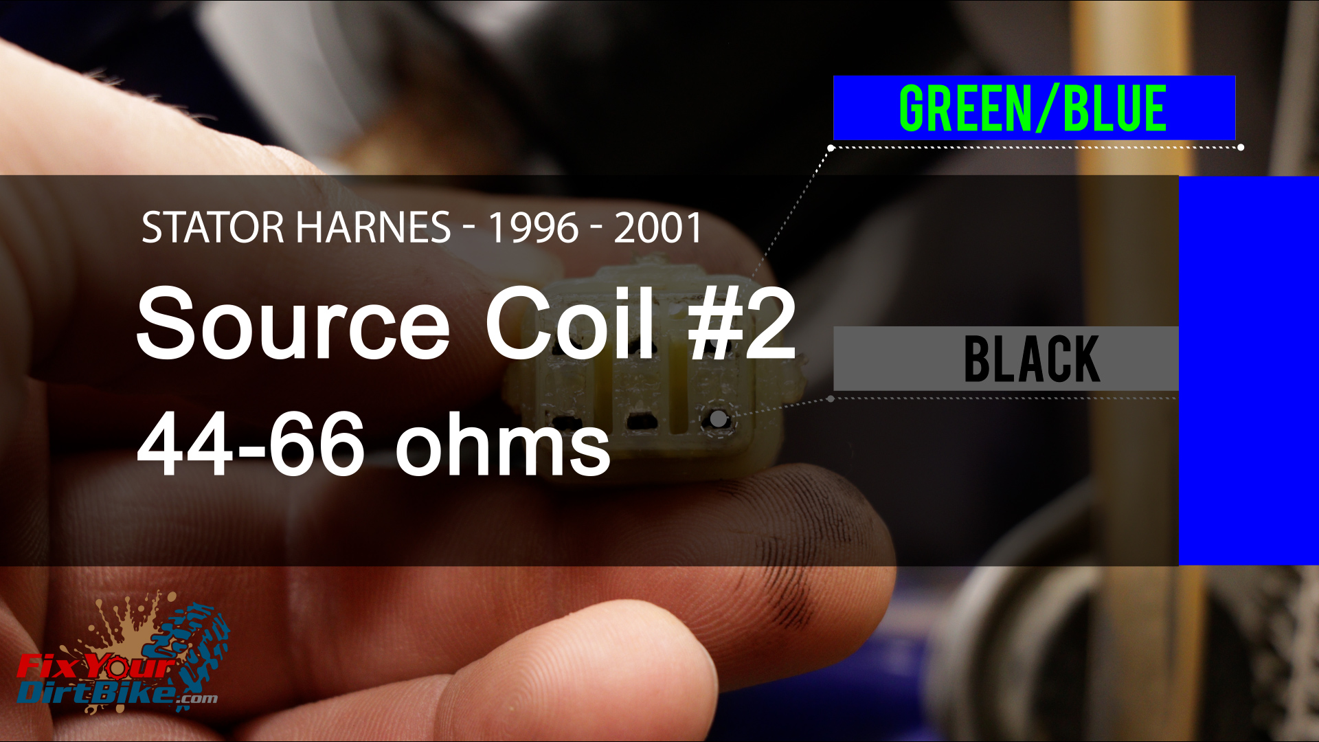
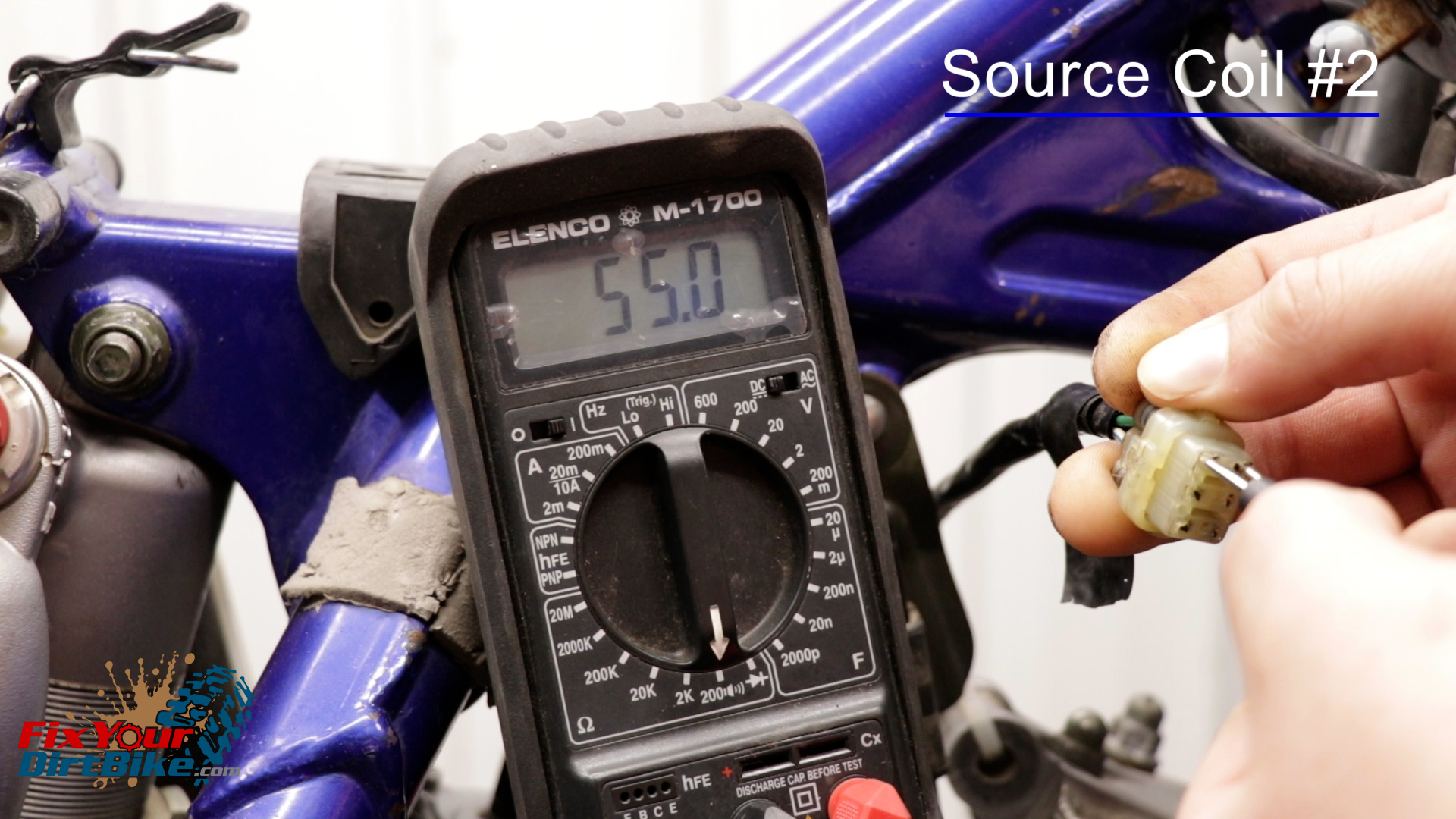
- Measure source coil #2 between the Black and Green/Blue wires.
- The resistance should measure between 44 to 66 ohms.
- My #2 coil metered at 55 ohms.
- The resistance should measure between 44 to 66 ohms.
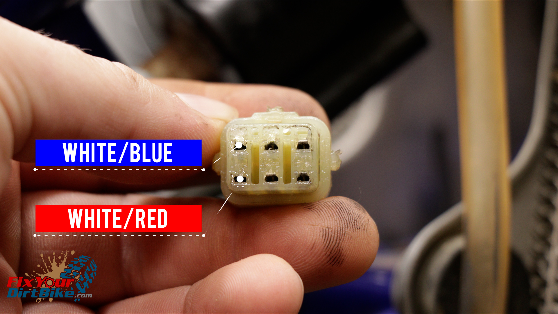
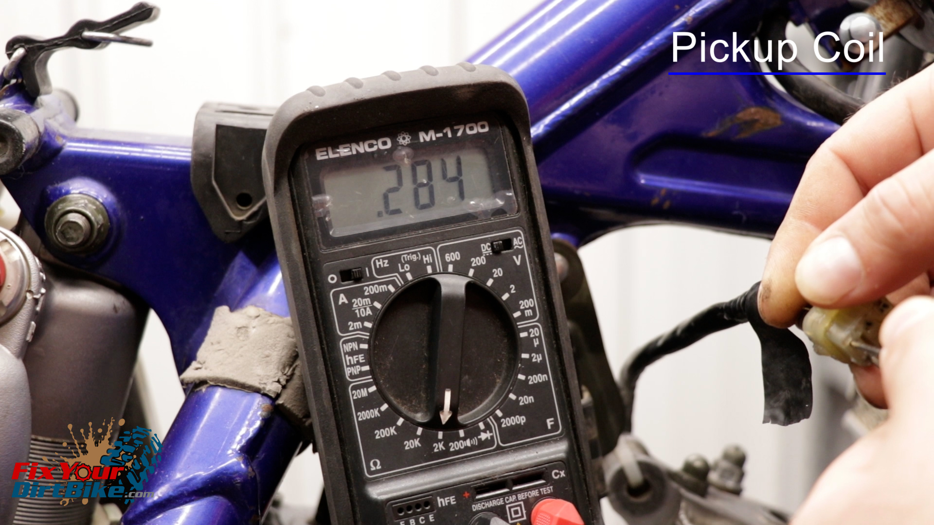
- Measure the Pickup Coil between the White/Blue and White/Red wires.
- The resistance should measure between 248 and 372 ohms.
- My pickup coil metered at 284 ohms.
- The resistance should measure between 248 and 372 ohms.
Test Results
- If any of the three coils measures out of spec, you will need to repair or replace the stator assembly.
- The good news is these stators can take a lot of abuse before failure.
- The bad news is if everything has tested out, you’ll need a new CDI.
Make sure you reconnect your wiring harness with plenty of dielectric grease!
You can follow me at Fix Your Dirt Bike across all social media, and If you have any questions, please let me know in the comments or direct message.


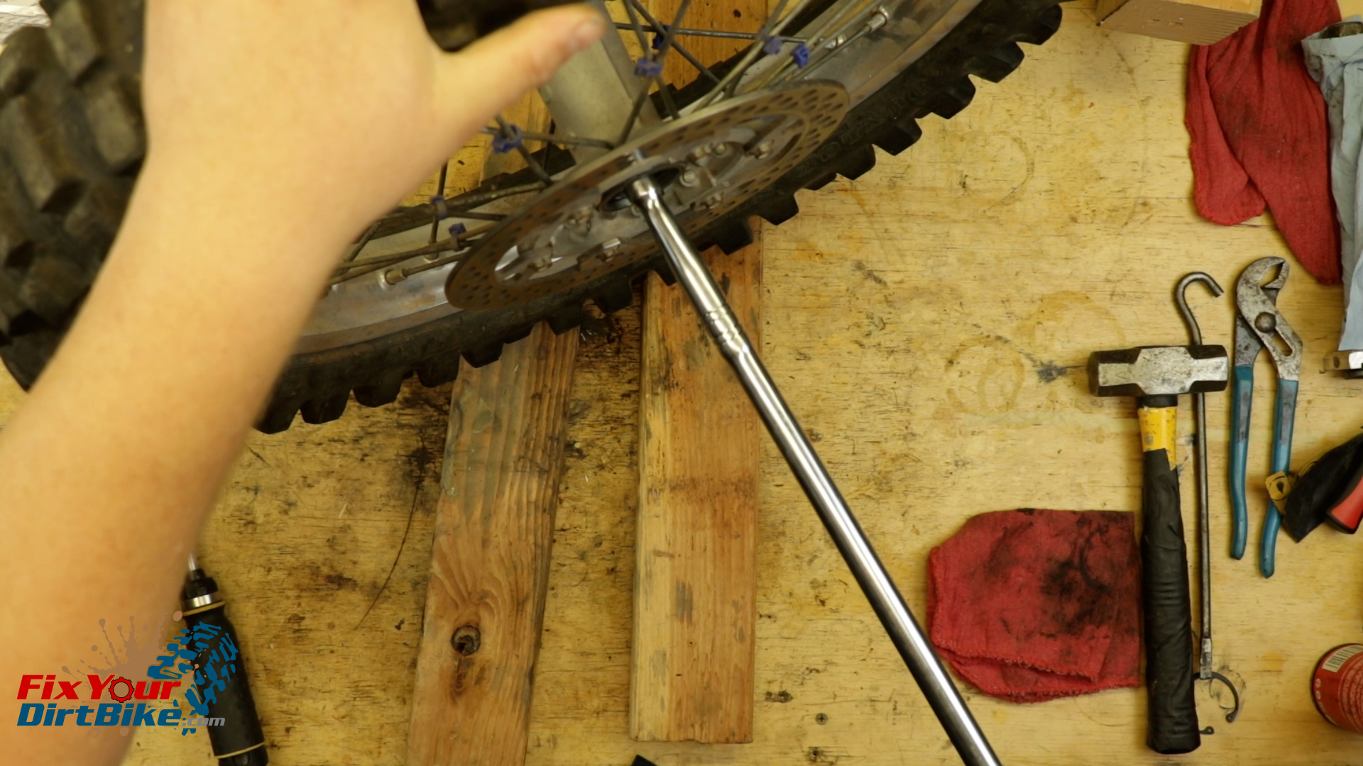
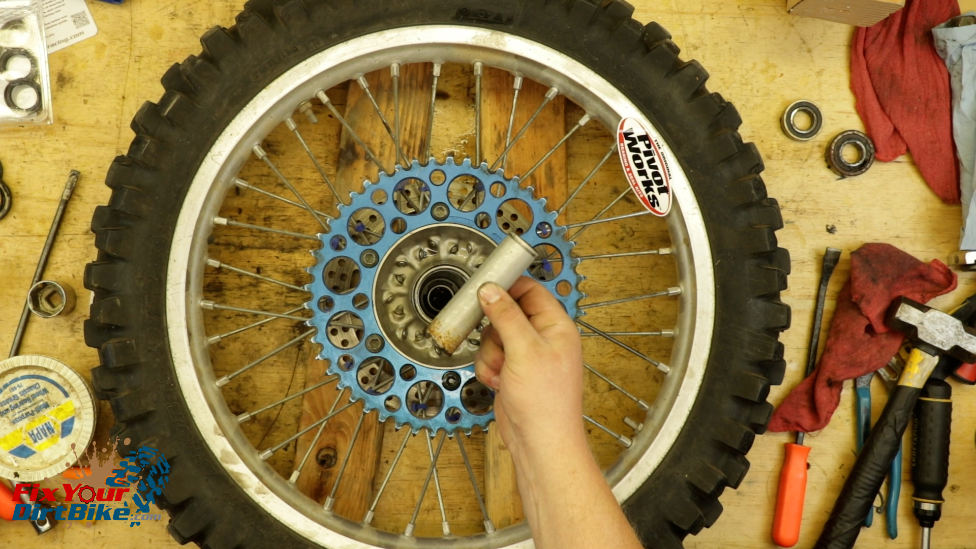

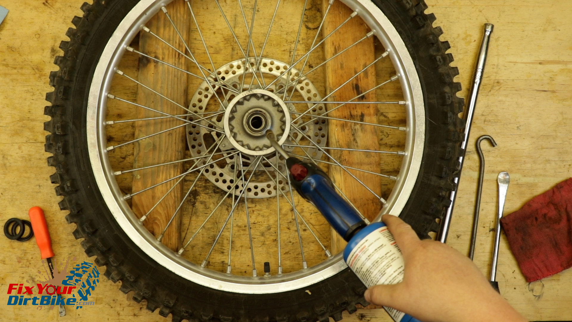
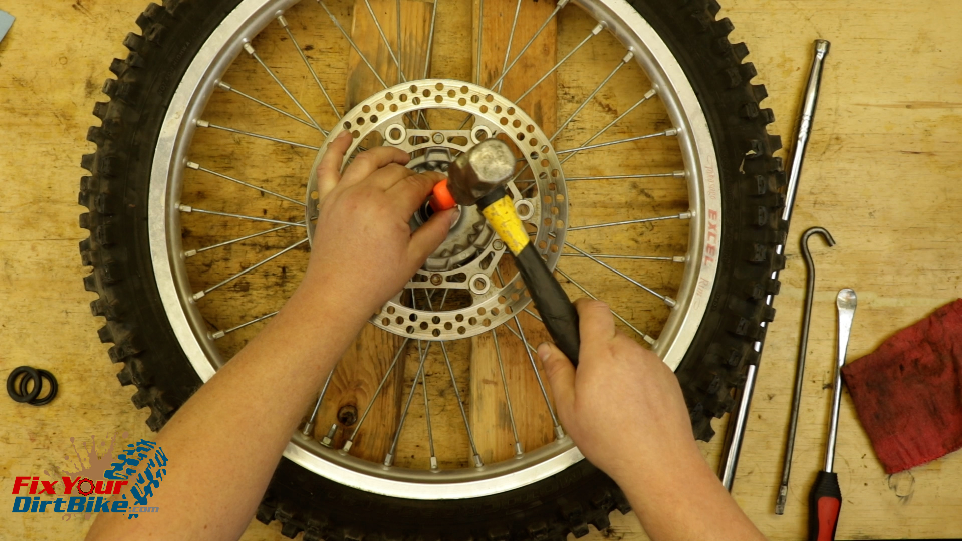
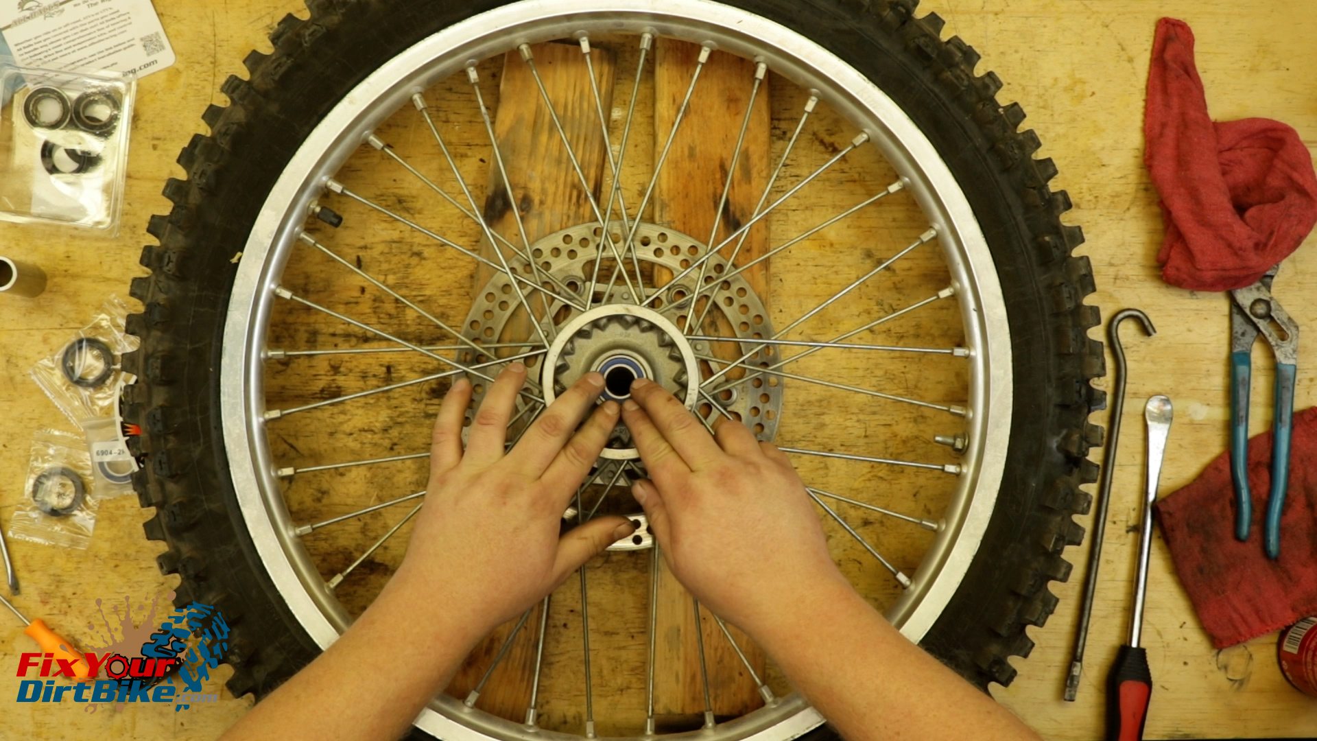
 Before you start this service, throw your bearing kit in the freezer for a few hours. Removing the front wheel bearings does require fire, so arrange your workspace accordingly!
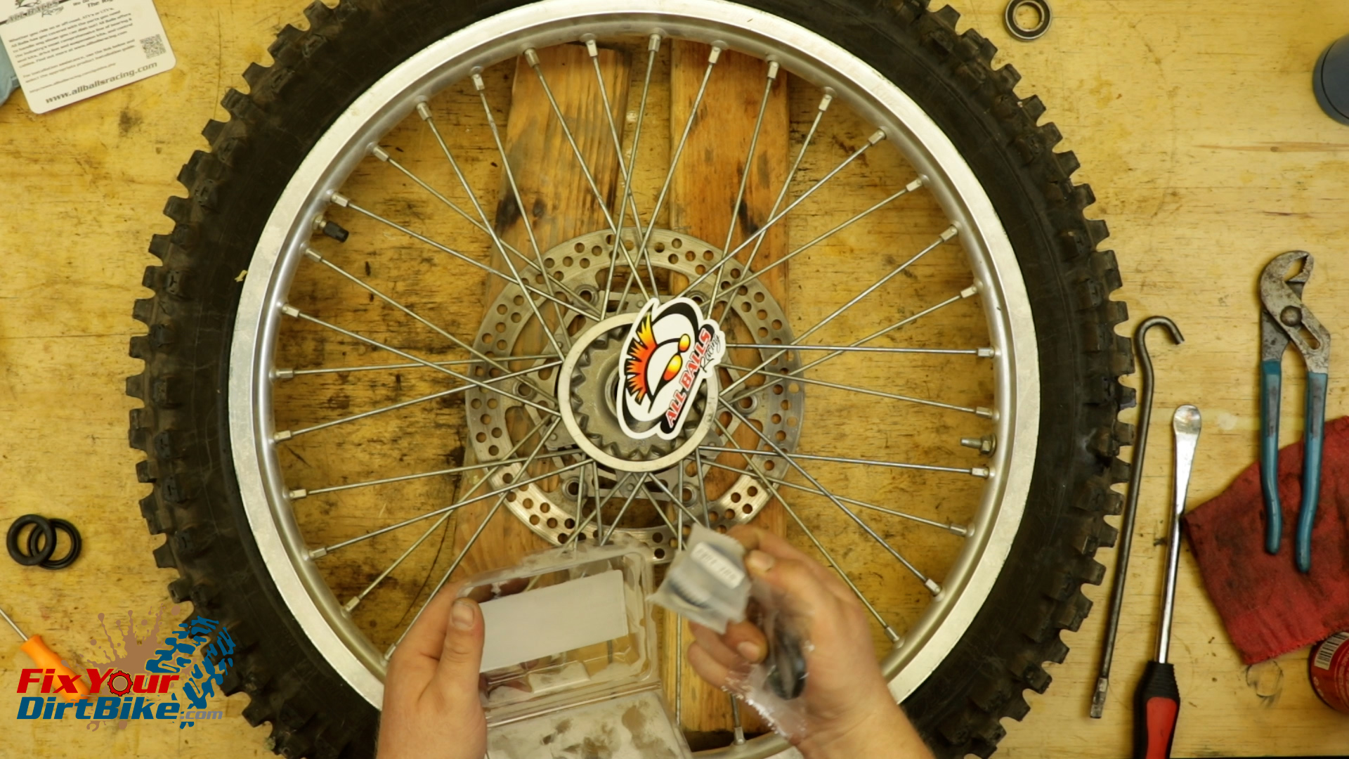
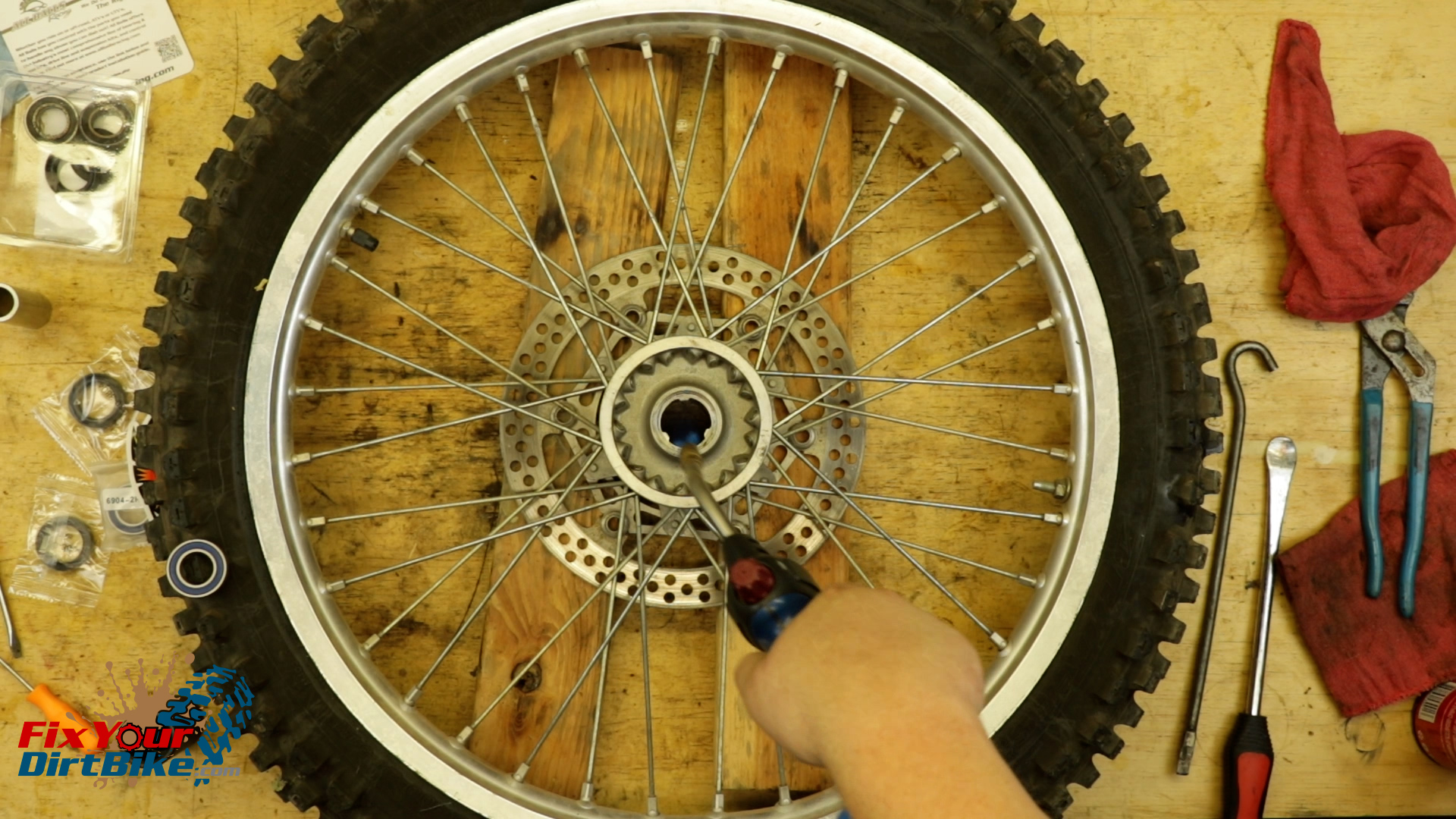
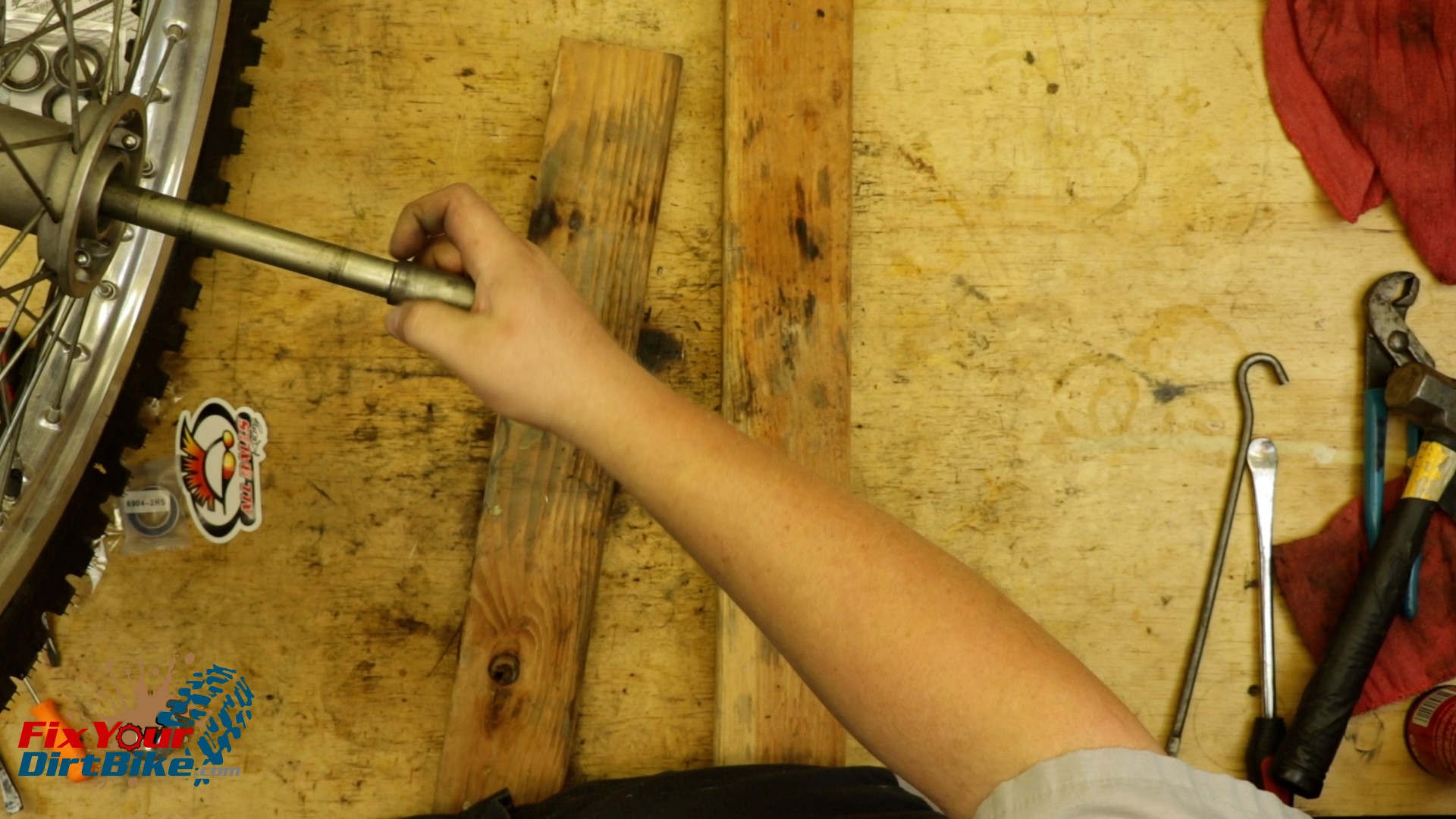


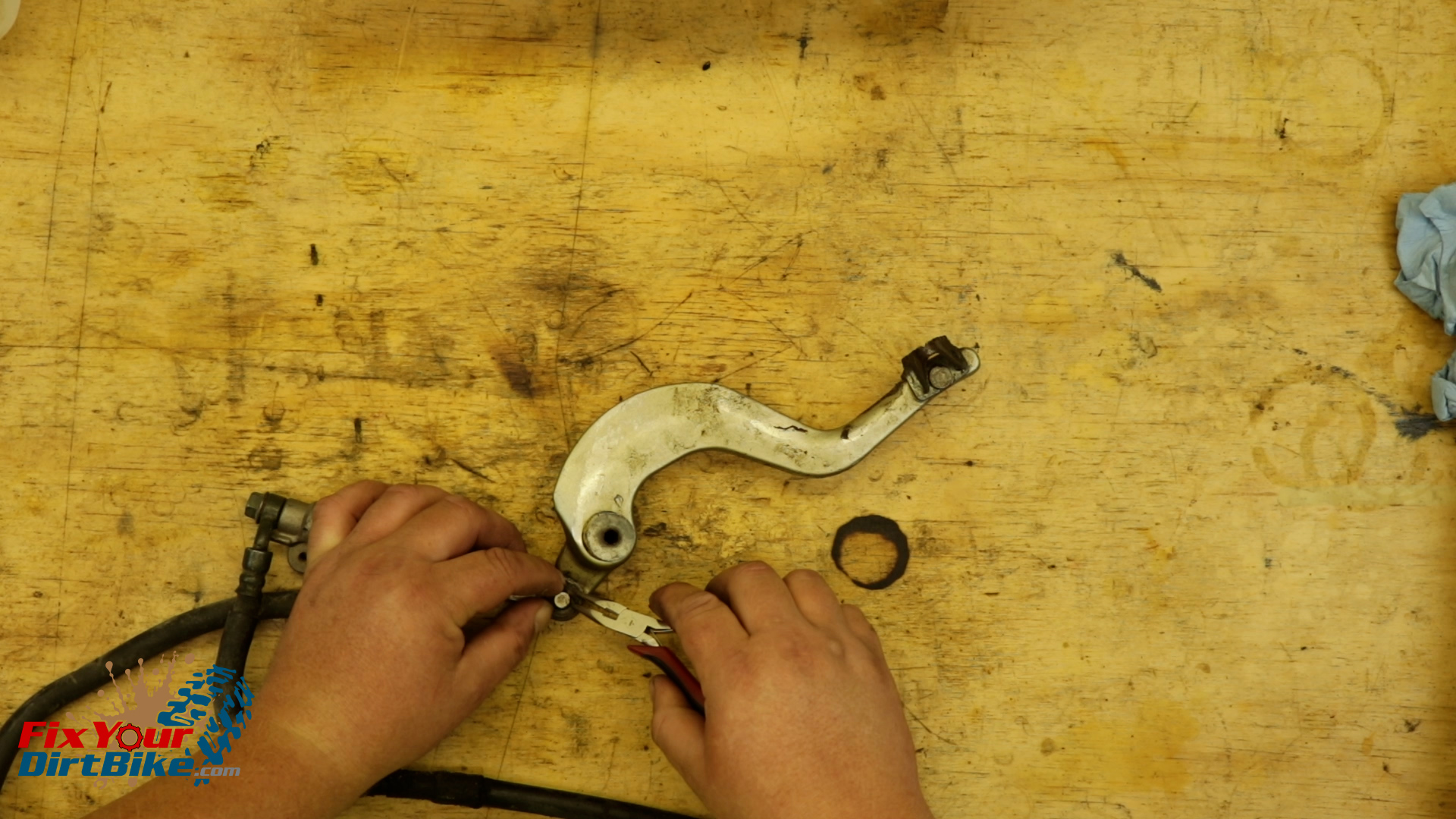
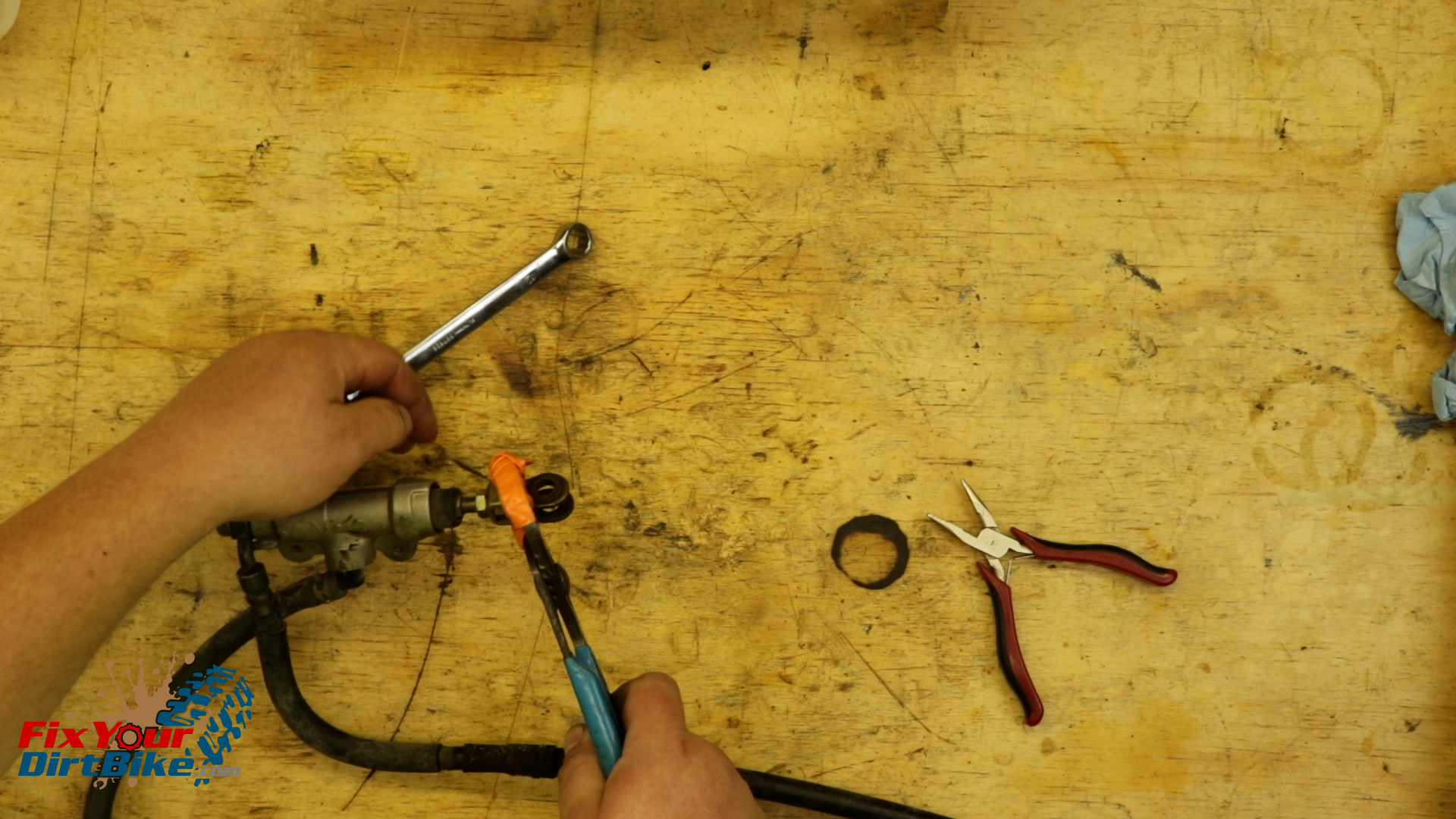
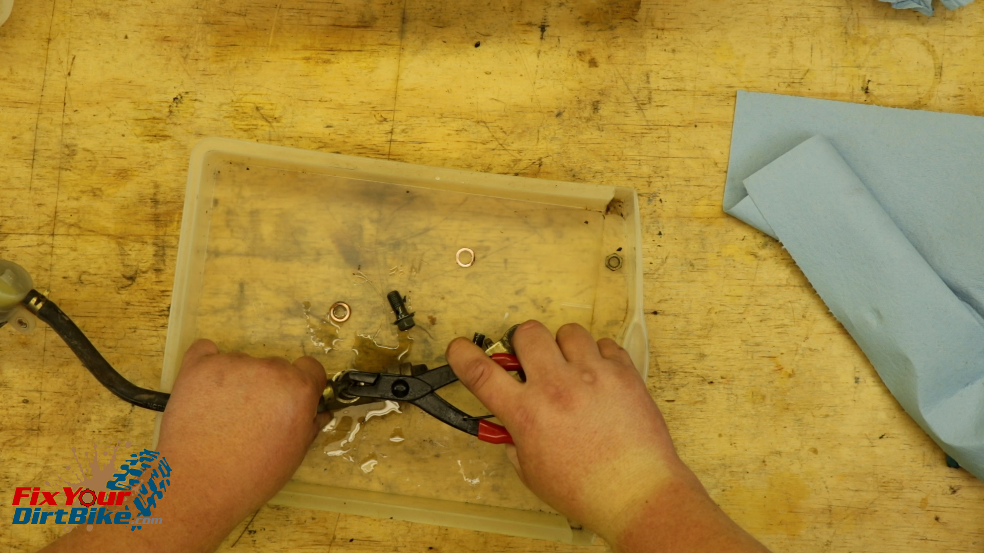
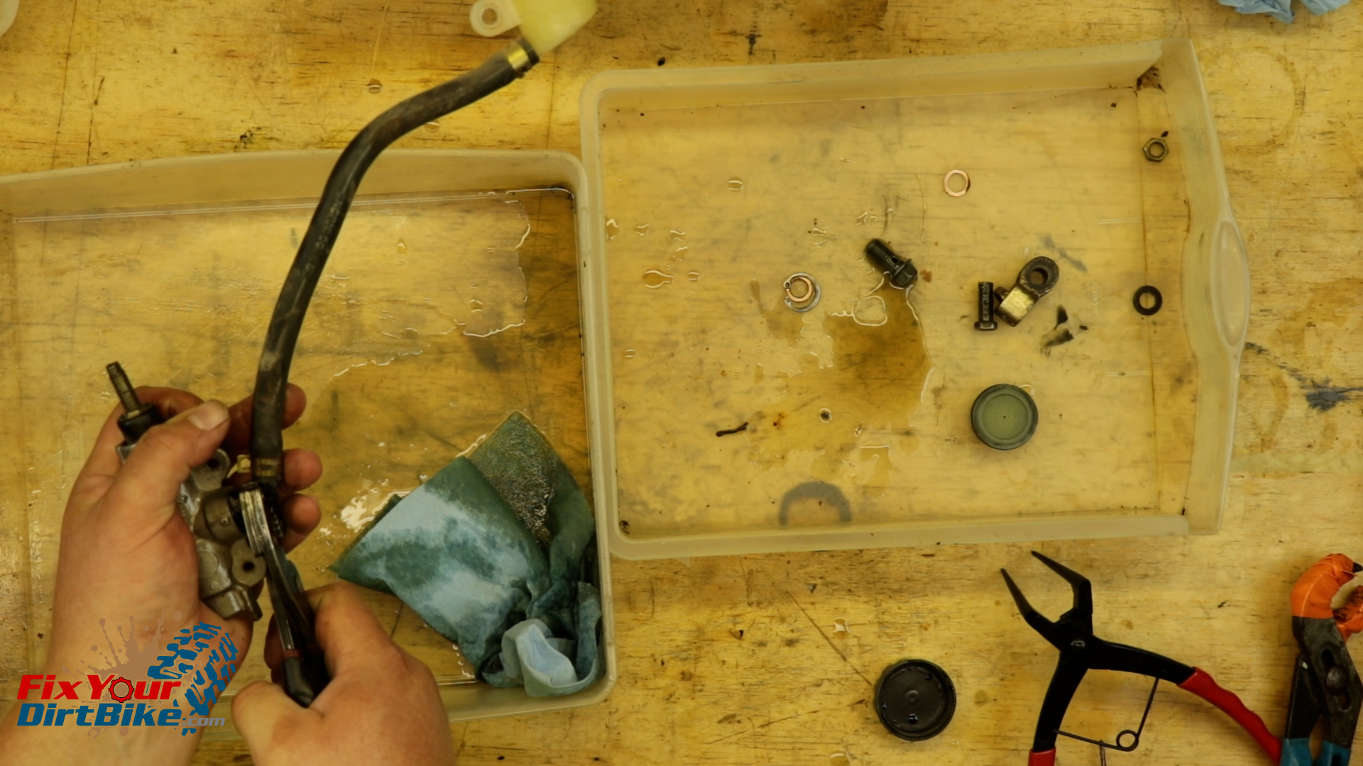
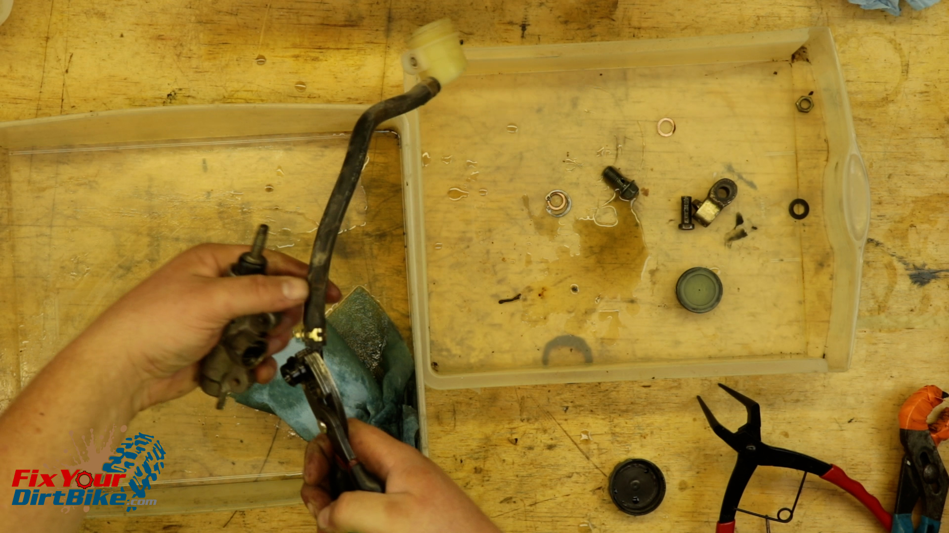
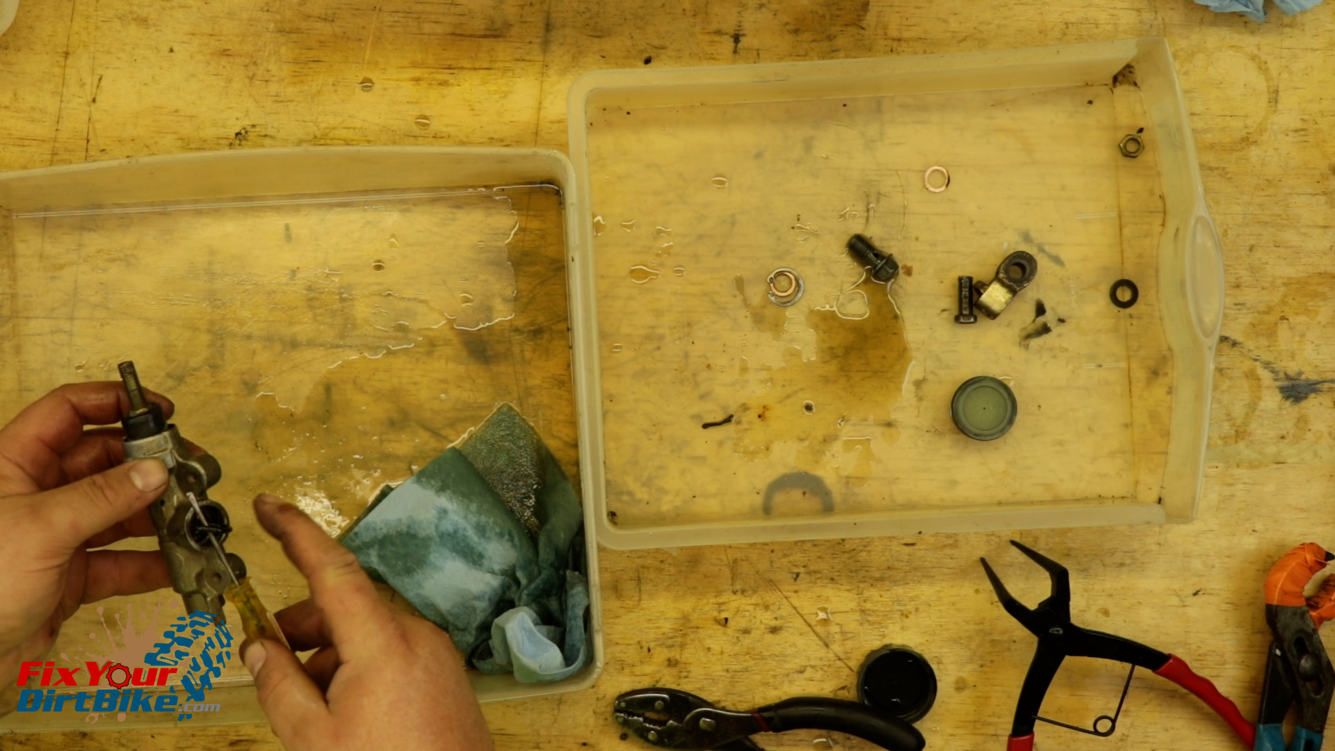
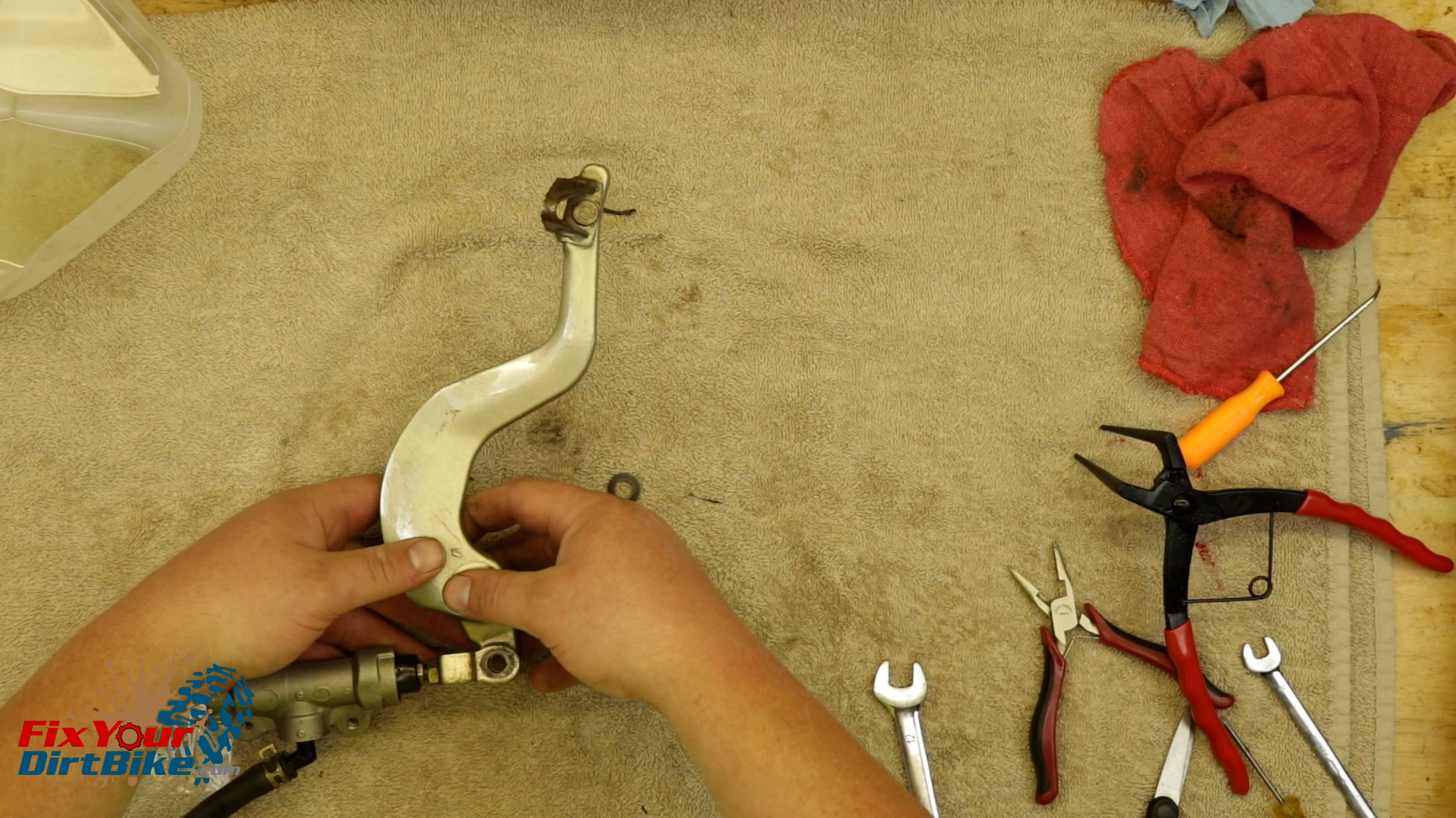
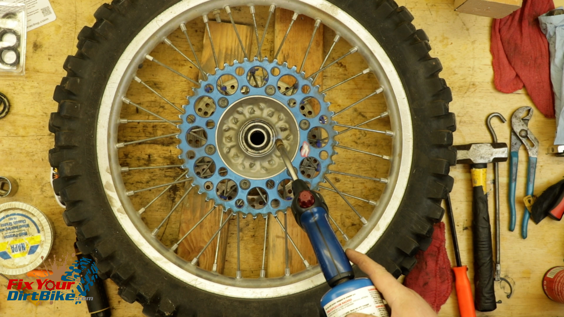
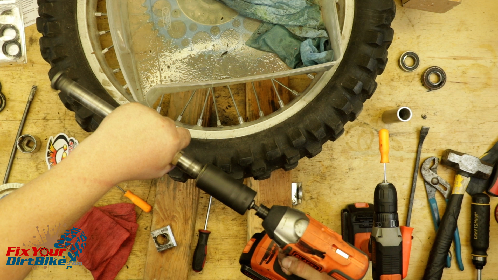
 My bike is stripped, so I am removing the banjo bolt on the bench, but I would recommend removing yours while still mounted to the bike.