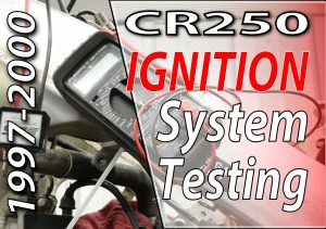
How To Troubleshoot The Electrical System On Your 1997 – 2001 Honda CR250
 I wanted to use my CR250 as an example of a fully functioning ignition system. My ignition coil died sometime in the past month, so that’s good timing.
The quickest way to determine if your ignition system is having issues is to remove your spark plug, ground it to the outside of the cylinder, turn the lights off, and kick your bike over.
If you have no spark or spark with low performance, this is how to troubleshoot the ignition system on your 1997 through 2001 Honda CR250.
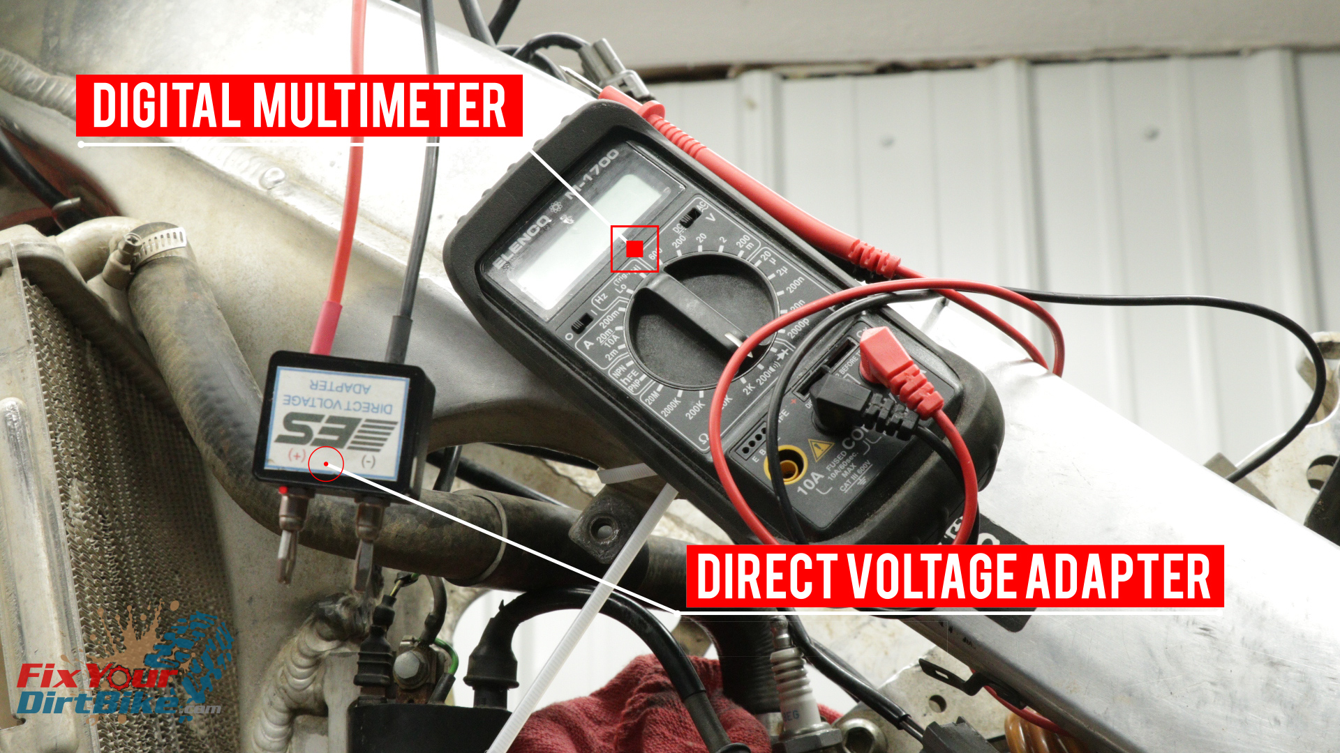
Troubleshooting Parts And Tools:
You will need a Digital Multimeter and a Direct Voltage Adapter to test your ignition. You can pick up both for around $60.
- Philips Head Screwdriver
- Tiny Flat Head Screwdriver
- 8mm Socket & Wrench
- Zip Ties
- Handy Wire
- Towel
- Multimeter → https://amzn.to/408cj1a
- Direct Voltage Adapter (AKA Peak voltage Adapter) → https://amzn.to/3C9BKaK
Effective Troubleshooting
Troubleshooting your ignition system only works when you stay organized, write everything down, and take your time. Otherwise, it can get frustrating very quickly.
To make troubleshooting as easy as possible, do not try to chase the problem. Test each component individually, and write down each test result as you go. Recording each result will let you find the problem on paper instead of jumping around between components.
When bleshooting each component, you must test each possible cause in ORDER.
Click here to open the Ignition System Specifications in a new window.
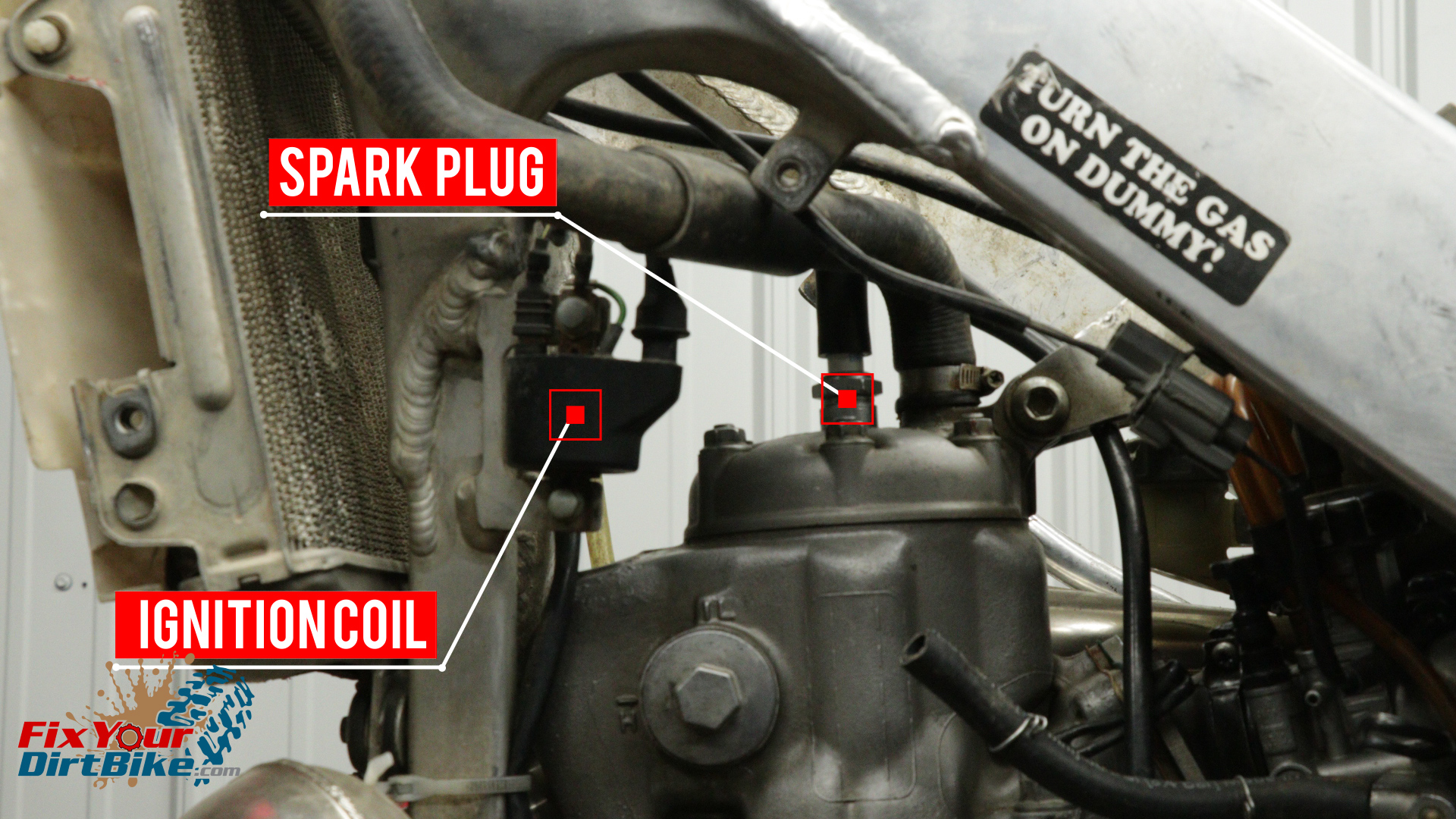
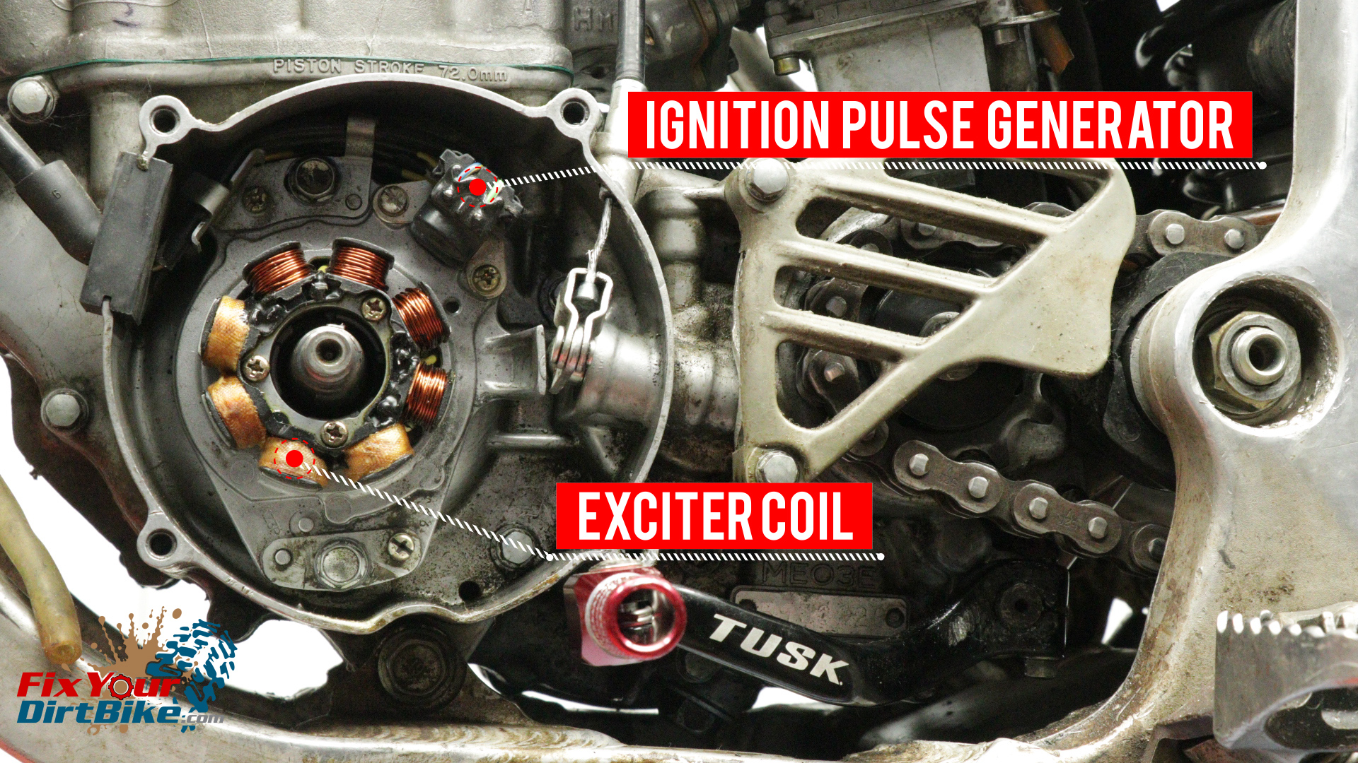
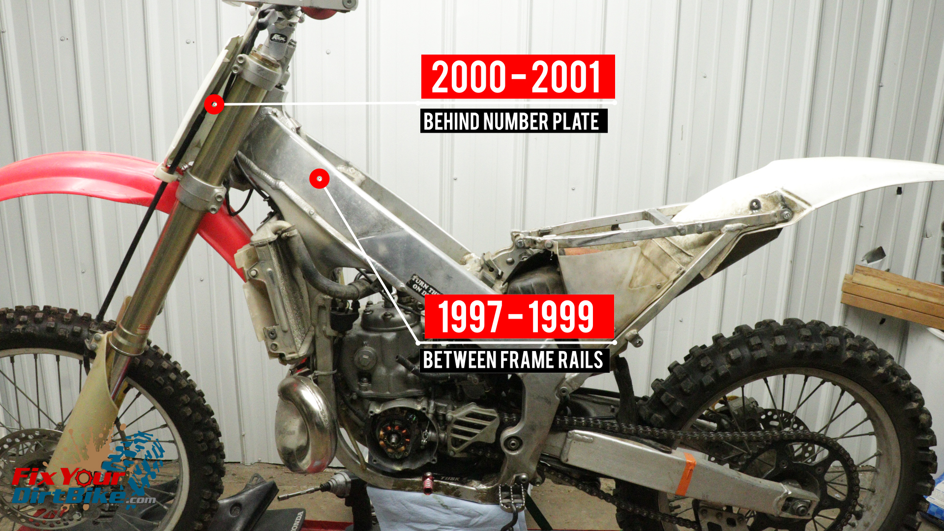
Component Locations
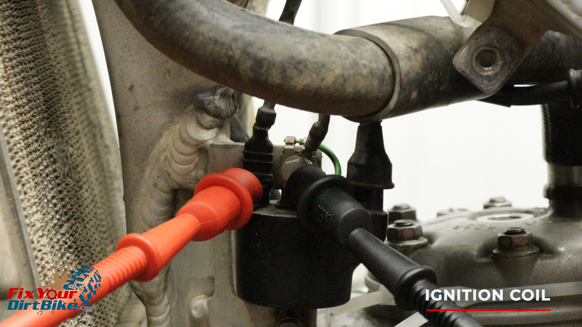
- The ignition coil is mounted on the front left of the frame.
- The exciter coil and ignition pulse generator are part of the stator and are mounted behind the flywheel.
- The ignition control module is mounted between the frame rails under the gas tank on 1997 – 1999 models and behind the number plate on 2000 – 2001 models.
Troubleshooting Prep
- Start by removing the flywheel cover and gas tank.
- You will be testing the stator through the wiring harness, so you DO NOT need to remove the flywheel or the stator.
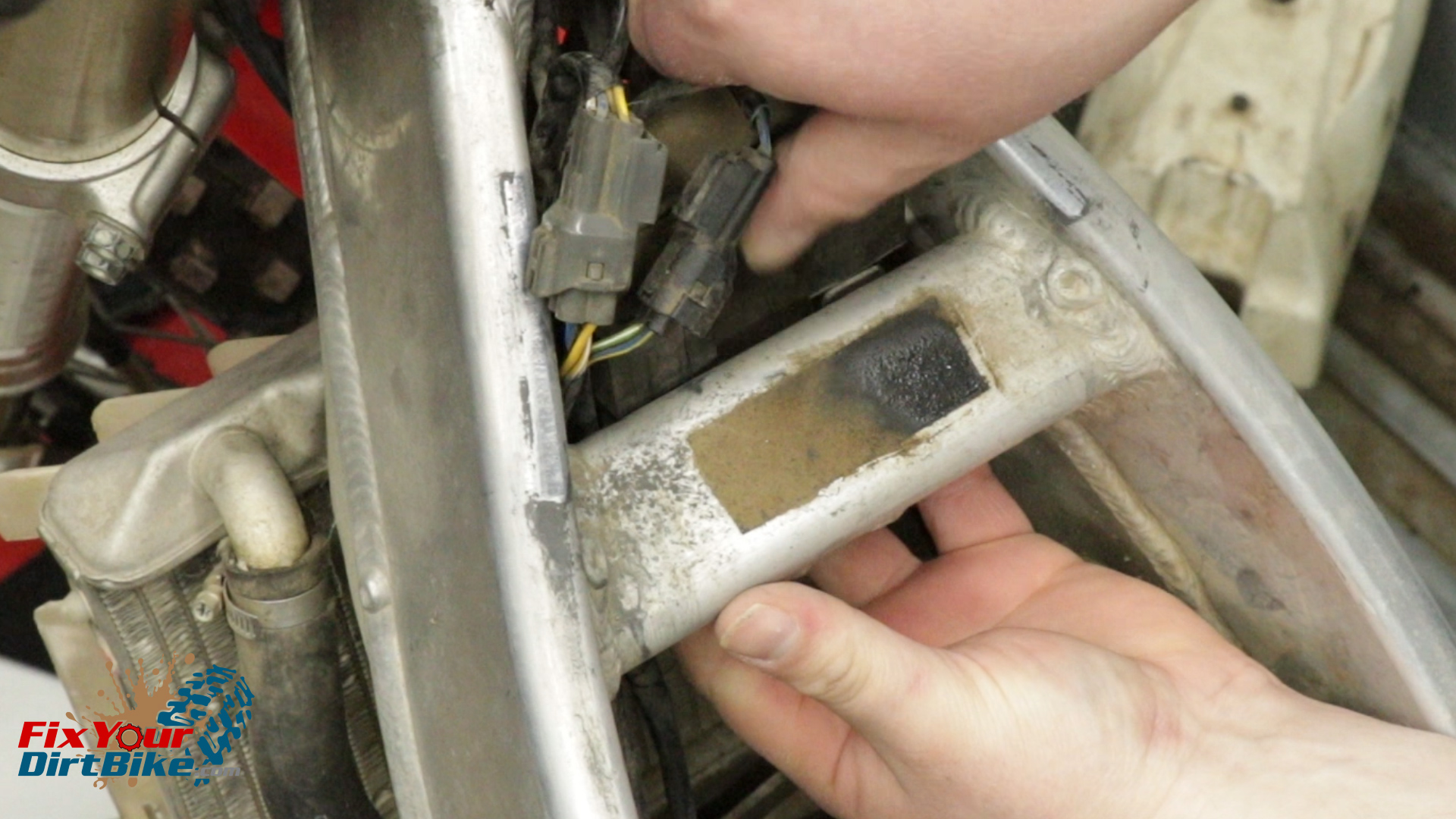
- To remove the Ignition control module, push the rubber mount up off the mounting tabs, then down and out toward the back of the bike.
- When testing peak voltage, you must be able to kick your bike over while keeping the test leads connected.
- If you don’t have a helper, strap your bike to something solid, zip tie your multimeter to your bike, and use handy wire in the gator clips of your direct voltage adapter as needed.
- Remove your spark plug and ground it to the cylinder.
- It is critical that you keep your spark plug grounded throughout testing! An ungrounded plug can destroy the ignition coil!
- Make sure you have a fresh spark plug, and cover the spark plug hole with a towel.
Ignition Control Module
The ignition control module, also known as a CDI, cannot be tested and is not serviceable. The only way to test it is by testing everything else. If every other component passes, then you know the Ignition module has gone bad.
Engine Stop Switch
- If you have no spark, test your engine stop switch first because that’s usually the problem.
- Set your multimeter to the lowest Ohm setting, and connect the leads to the tails.
- While holding the leads to the tails, push the stop switch.
- The meter should show continuity when the button is pushed. The stop switch is terrible if you read continuity without pressing the button.
 Ignition Coil Testing
Test The ignition coil for peak voltage and resistance between three points.
- Primary to Ground
- Primary to Plug Boot
- Primary to Plug Wire
Ignition Coil Peak Voltage Test
- To test peak voltage, connect your positive test lead to the black/yellow primary terminal and the negative test lead to the ground bolt.
- Set your multimeter to 200 volts DC.
- Kick your bike over as fast as possible to get an accurate reading.
- Your ignition coil peak voltage should be at least 100 volts.
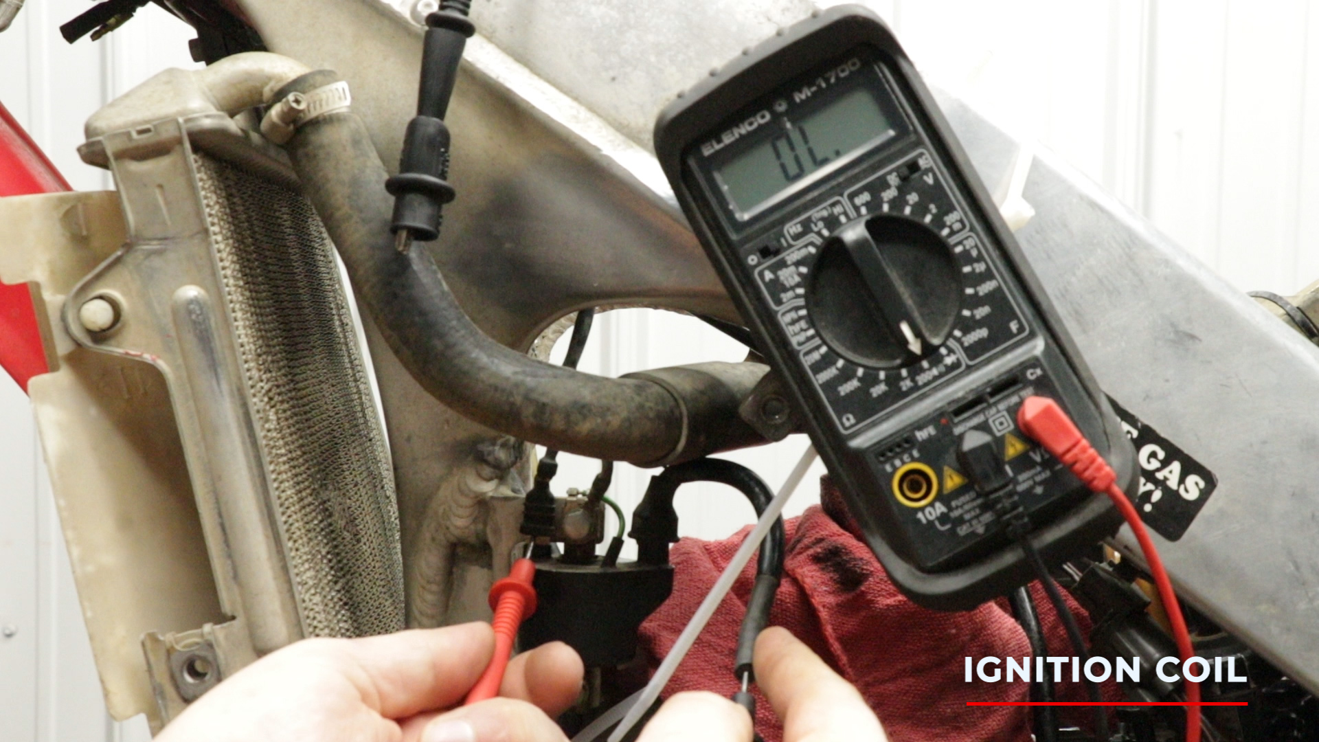
Ignition Coil Resistance Test
- Remove the direct voltage adapter from your multimeter to test the primary coil resistance, then connect the standard test leads.
- Set your multimeter to 200 Ohms.
- Touch the positive test leads to the primary terminal, and the negative test leads to the ground bolt.
- Your primary ignition coil should be between 0.2 and 0.4 Ohms on 1997-1999 models and 0.1 and 0.3 Ohms on 2000-2001 models.
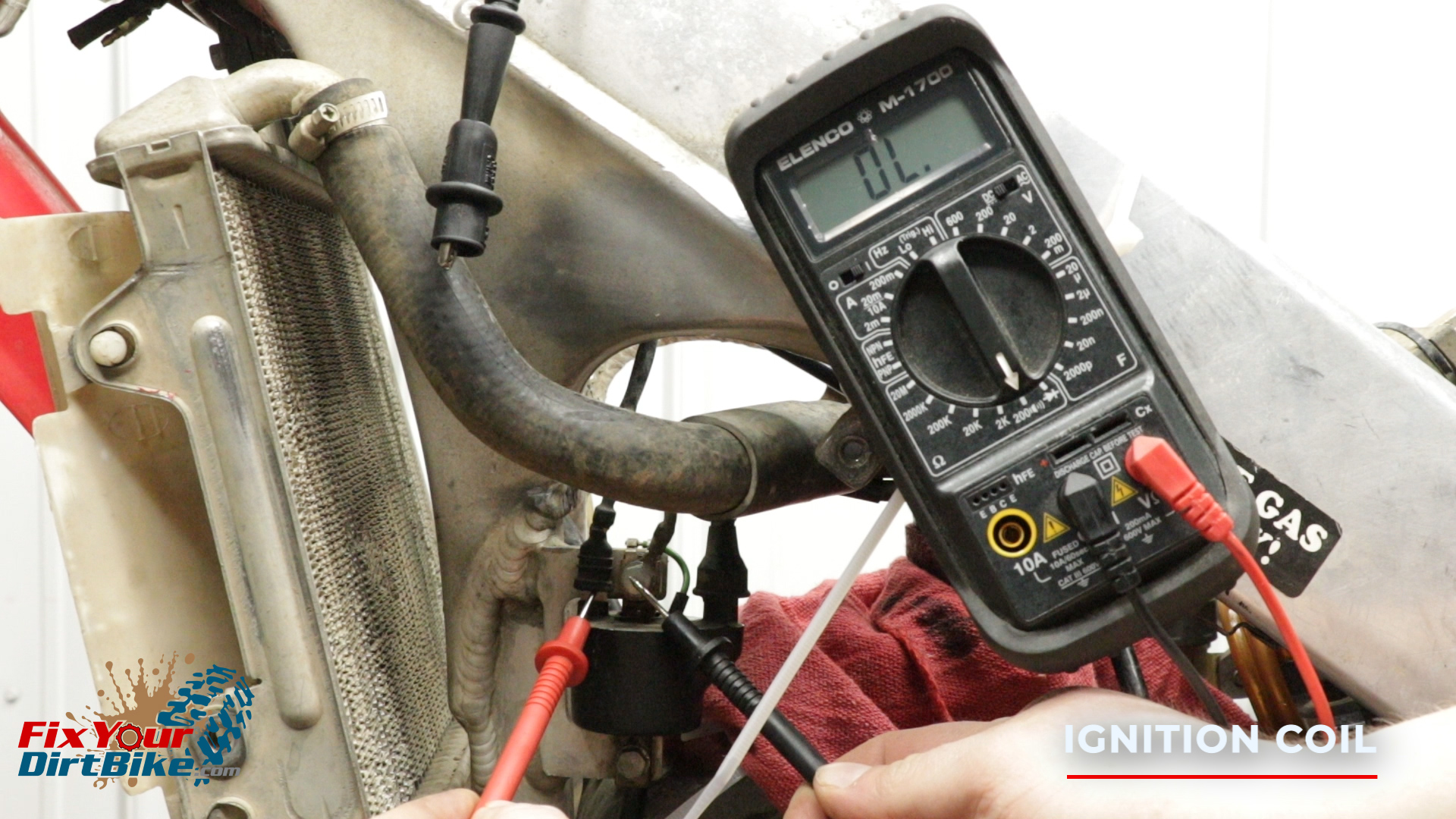
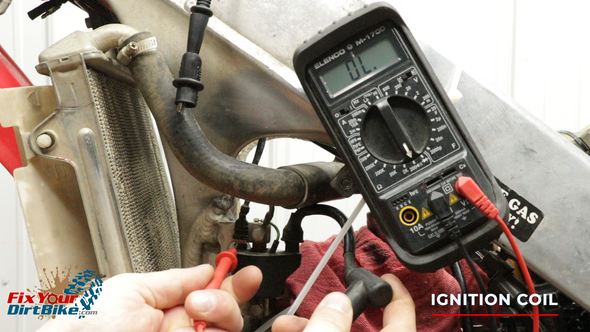
- To test the secondary coil, keep the positive test lead on the primary terminal and touch the negative test lead to the connection inside the spark plug boot.
- Your secondary coil should be between 9 and 16 ohms with the spark plug boot connected.
- Remove the spark plug boot, and insert the negative test lead into the end of the plug wire.
- Without the spark plug boot, your secondary coil should be between 4 and 8 ohms.
Ignition Coil Troubleshooting
If Your Ignition Coil Shows A Low Peak Voltage, Check The Following In Order:
- Bad Direct Voltage Adapter Connections
- Meter Impedance Is Too Low
- Cranking Speed Is Too Low
- Test And Pulse Not Synchronized (If Measured Voltage Is Over Minimum Once The System Is Normal)
- Poor Connection Or Open Circuit
- Bad Exciter Coil
- Bad Ignition Coil
- Bad Ignition Control Module (When All Others Check Out)
If Your Ignition Coil Shows No Peak Voltage, Check The Following In Order:
- Bad Direct Voltage Adapter Connections
- Short In Engine Stop Switch
- Bad Engine Stop Switch
- Poor Ignition Control Module Connection
- Open Circuit Or No Ground Of Ignition Control Module
- Bad Direct Voltage Adapter
- Bad Exciter Coil
- Bad Ignition Pulse Generator
- Bad Ignition Control Module
If You Are Reading Correct Voltage With No Spark:
- Bad Spark Plug
- Leaking Ignition Coil Secondary Current
- Bad Ignition Coil
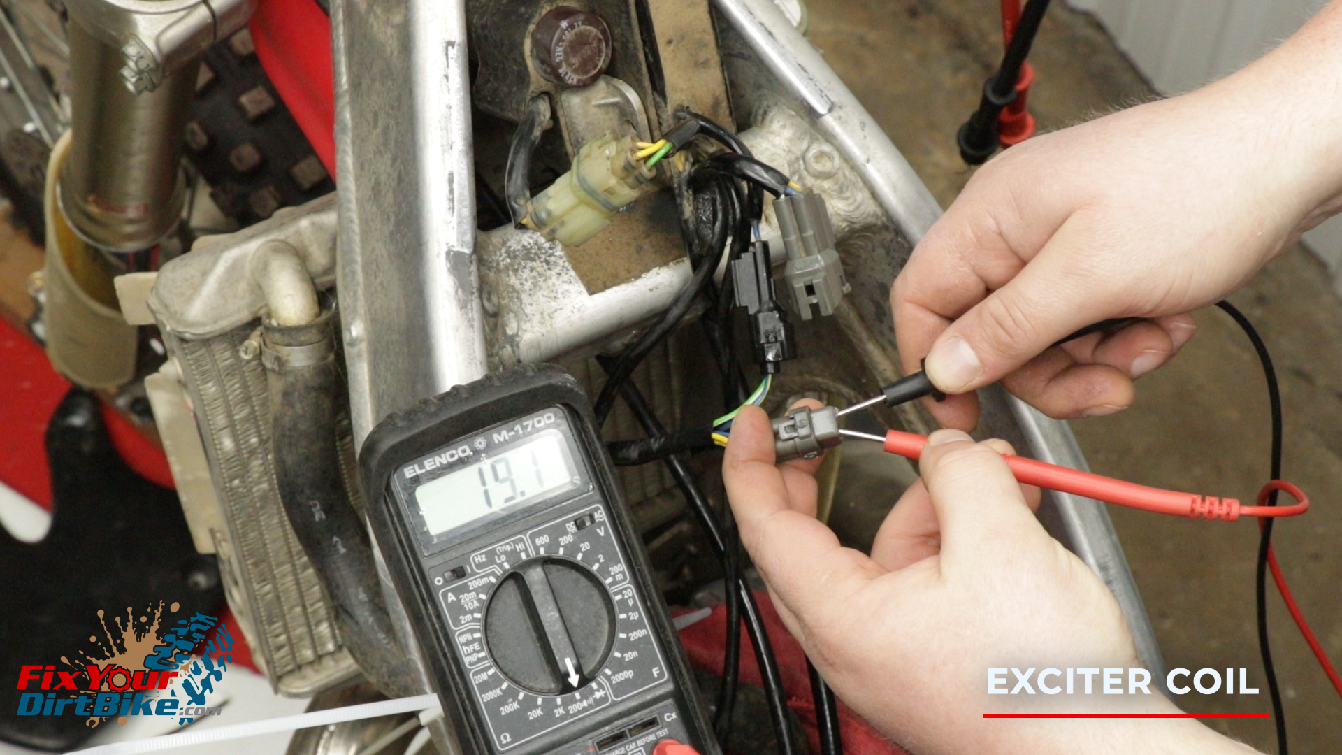
Exciter Coil Testing
Exciter Coil Peak Voltage Test
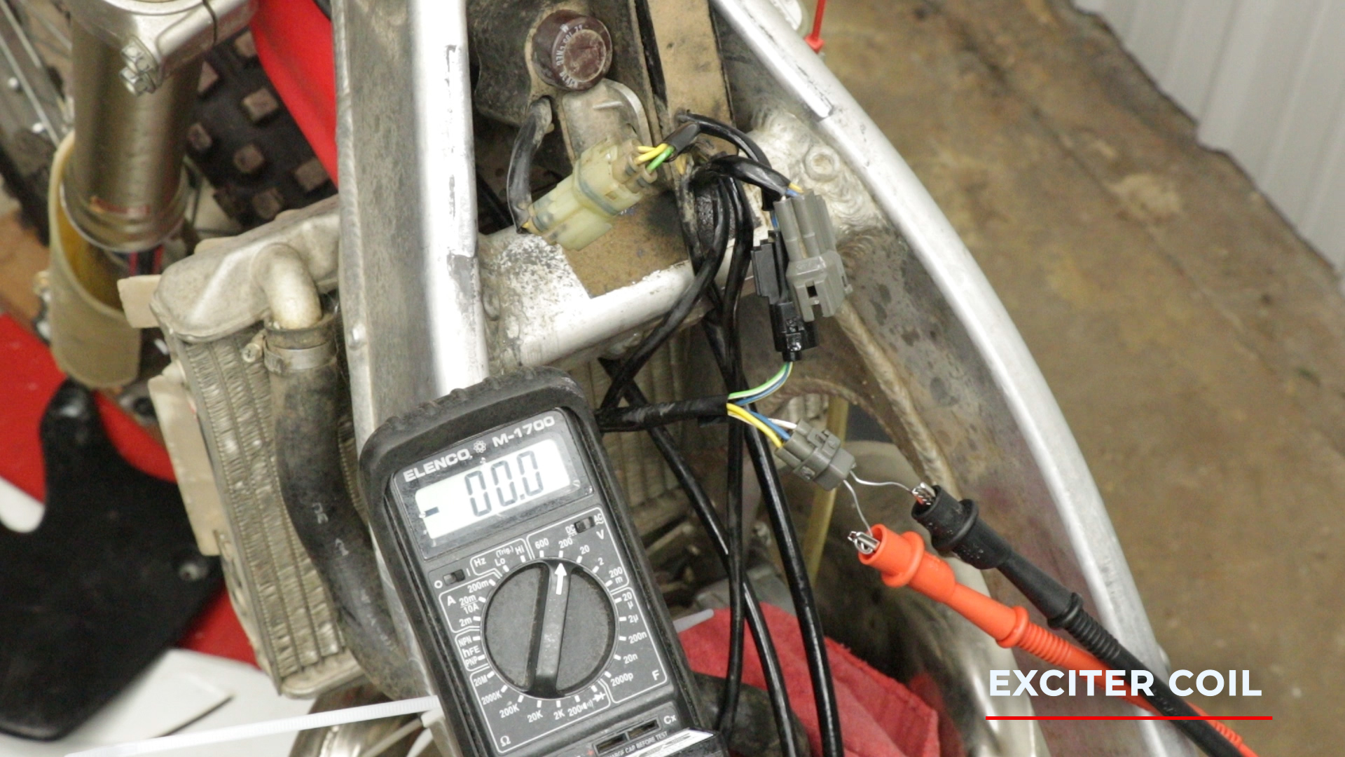
- The exciter coil is part of the stator, but you will test it at the ignition control module.
- Disconnect the wiring harness with the blue and white wires.
- To test the exciter coil peak voltage, connect your direct voltage adapter to your multimer and set it to 200 volts DC.
- Connect the positive test lead to the blue wire terminal and the negative test to the white wire terminal.
- Be sure to connect the leads under the connections, and the wire extensions should reach about ¼ inch into the harness.
- Kick your bike over and record the peak voltage.
- The exciter coil peak voltage should be at least 100 volts.
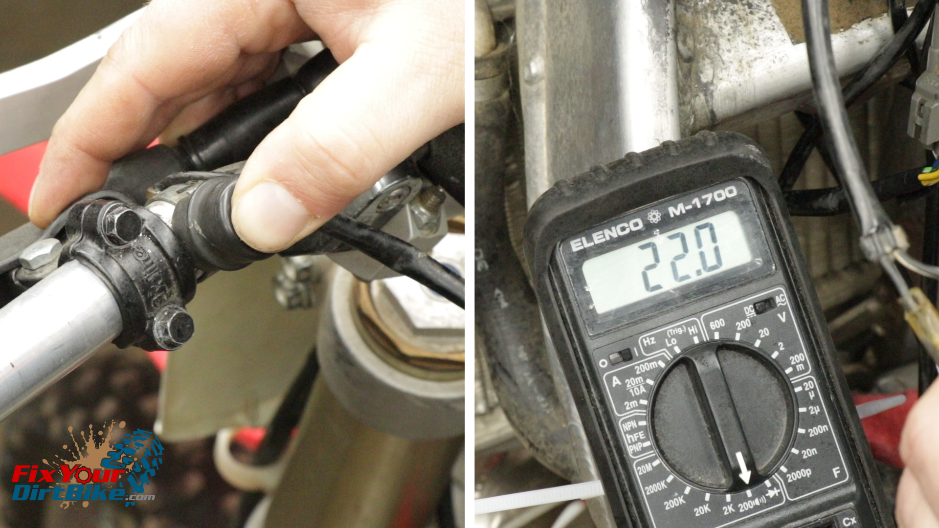
Side Note:
Unfortunately, it’s tough to get a reliable reading on the exciter coil peak voltage because you cannot kick your bike over fast enough. When starting your bike, you only have to kick once or twice, and then inertia takes over, and the bike does the rest.
As you can see here, I am kicking the absolute shit out of my bike and barely reading over 20 volts. So consider this when troubleshooting on paper, and return to it if needed.
Exciter Coil Resistance Test
- To test the exciter coil’s resistance, use the standard test leads and set your multimeter to 200 Ohms.
- Connect the positive test lead to the blue wire terminal and the negative test to the white wire terminal.
- The resistance should be between 2 and 20 Ohms on 1997 through 1998 models and between 9 and 25 Ohms on 1999 through 2001 models.
- Apply dielectric grease to the inside of the wiring harness and reconnect the exciter coil.
Exciter Coil Troubleshooting
If Your Exciter Coil Shows A Low Peak Voltage, Check The Following In Order:
- Meter Impedance Is Too Low
- Cranking Speed Is Too Low
- Test And Pulse Not Synchronized (If Measured Voltage Is Over Minimum Once The System Is Normal)
- Bad Ignition Control Module
If Your Exciter Coil Shows No Peak Voltage, Check The Following In Order:
- Bad Direct Voltage Adapter
- Bad Exciter Coil
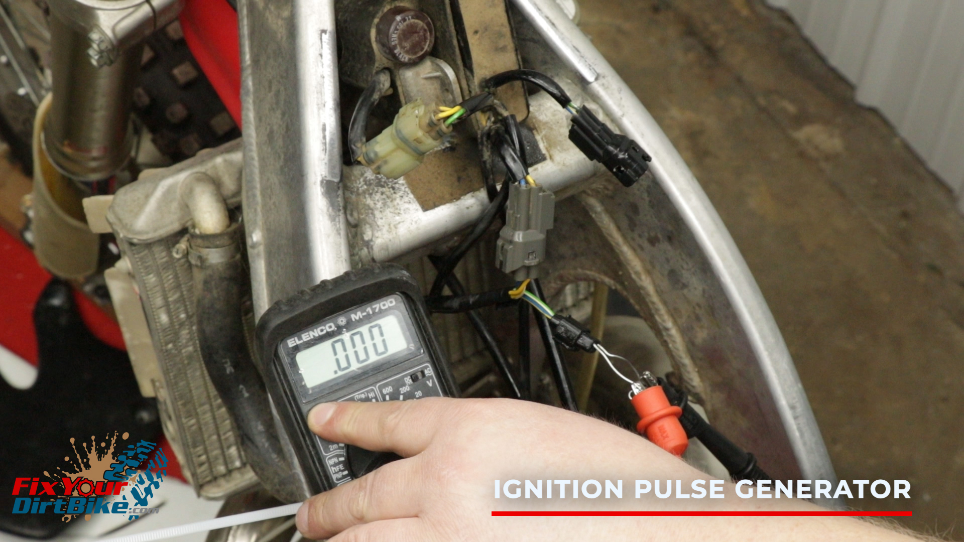
Ignition Pulse Generator
The ignition pulse generator is part of the stator, but you will test it on the ignition control module. Disconnect the wiring harness with the blue/yellow and green/white wires.
Ignition Pulse Generator Peak Voltage Test
- To test the ignition pulse generator peak voltage, connect your direct voltage adapter to your multimer, and set it to 2 volts DC.
- Connect the positive test to the blue/yellow wire terminal and the negative test to the green/white wire terminal.
- Kick your bike over and record the peak voltage.
- The ignition pulse generator’s peak voltage should be at least 0.7 volts.
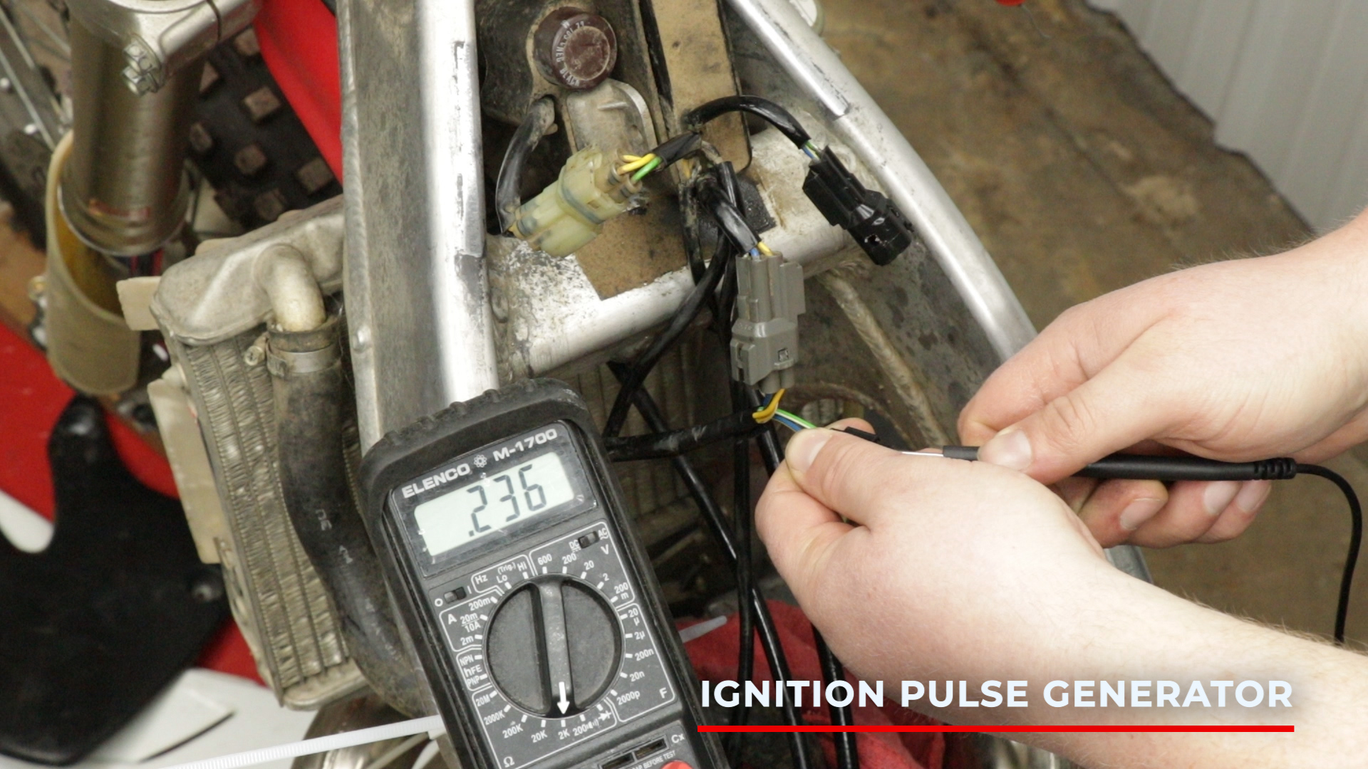
Ignition Pulse Generator Resistance Test
- To test the resistance of the ignition pulse generator, use the standard test leads and set your multimeter to 2,000 (2K) Ohms.
- Connect the positive test to the blue/yellow terminal and the negative test to the green/white terminal.
- The resistance should be between 180 and 280 ohms.
- Apply dielectric grease to the inside of the wiring harness and reconnect the ignition pulse generator.
Ignition Pulse Generator Troubleshooting
If Your Ignition Pulse Generator Shows A Low Peak Voltage, Check The Following In Order:
- Meter Impedance Is Too Low
- Cranking Speed Is Too Low
- Test And Pulse Not Synchronized (If Measured Voltage Is Over Minimum Once The System Is Normal)
- Bad Ignition Control Module
If Your Ignition Pulse Generator Shows No Peak Voltage, Check The Following In Order:
- Bad Direct Voltage Adapter
- Bad Ignition Pulse Generator
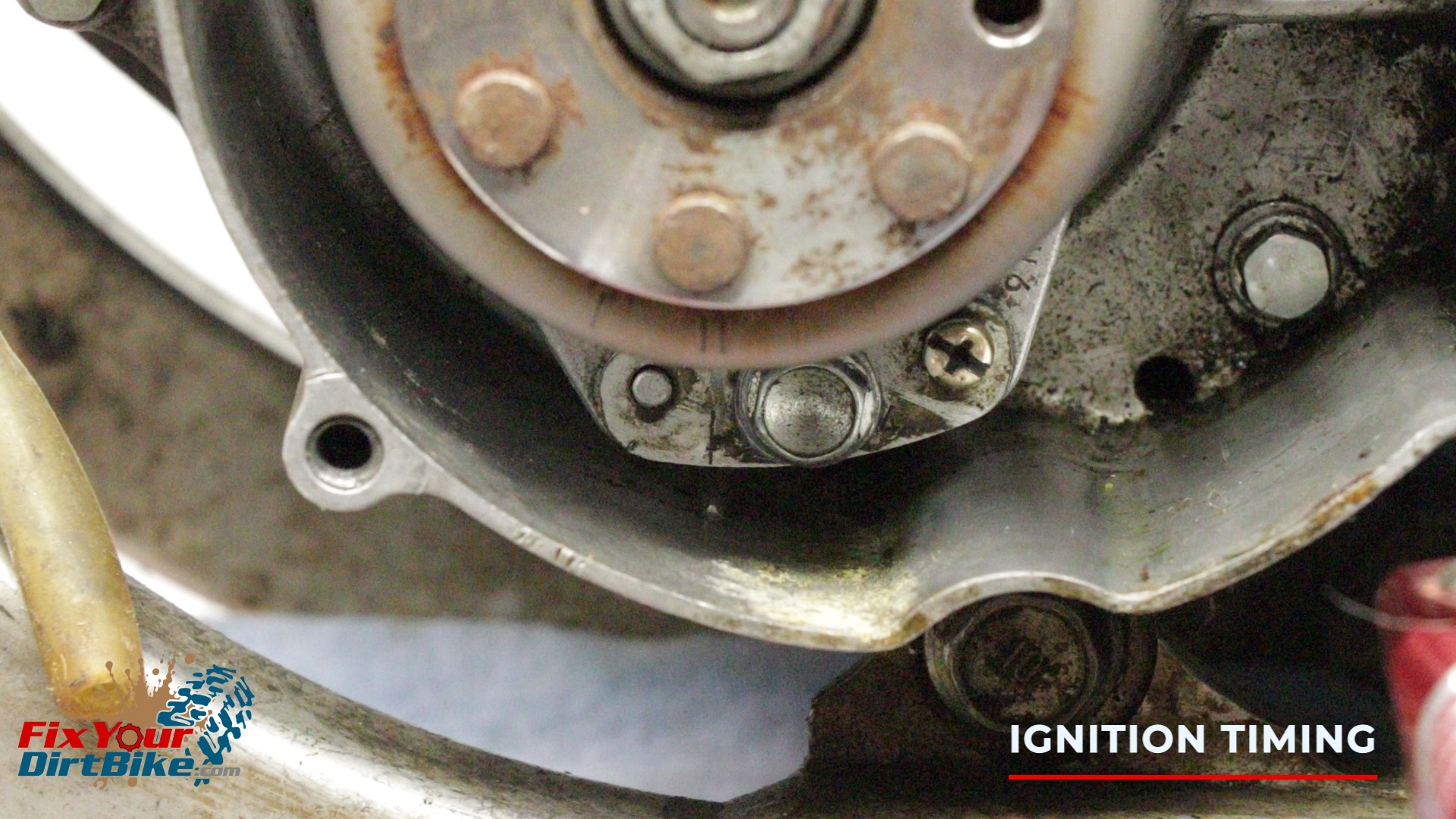
Ignition Timing
You will need a timing gun and a tachometer to read and adjust the timing fully. Or, you can make sure the tab on the crankcase and the mark on the stator are aligned and call it a day.
If you have an aftermarket flywheel, ensure the magnet lines up with the ignition pulse generator and the double scribe marks line up to the stator. While not impossible, it is highly improbable that the timing would be off if your CR is stock.
Power Jet Solenoid
I did not cover the power jet solenoid for two reasons:
- It only came on 97 and 98 models
- It never really worked when it did work
If you want to test your power jet solenoid, message me on Facebook, and I’ll be happy to help.
If you have any questions or need help troubleshooting your ignition system, please let me know in the comments or on social media.
Keep Your ’97-’01 CR250 Running Right!
- Service Specification
- Clutch Replacement
- Carburetor Service
- Engine Top End
- Engine Bottom End
- Brakes
- Exhaust
- Front Suspension
- Rear Suspension
- Wheels & Tires
- Kickstarter Inspection
- External Shift Linkage