This is PART 3 of the step-by-step rebuild for your Showa KZ3P SA-1 rear shock.
You can find Part 1: Disassembly & Inspection here, and Part 2: Shaft Assembly here.
Remember, if you need parts and tools, you can get them HERE.
Click Here To Open The Rear Suspension Specifications In A New Window
1997-2001 Honda CR250 Rear Shock Assembly
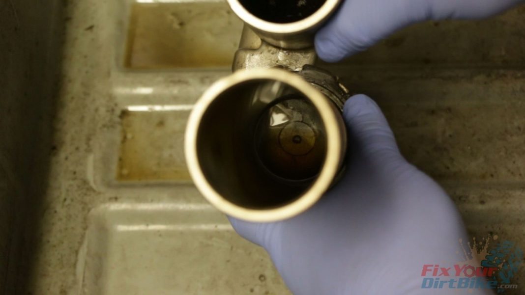
- Step 16: Back out the compression damper all the way to allow open oil flow between the reservoir and the body.
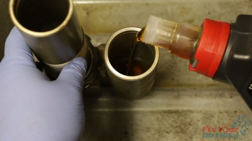
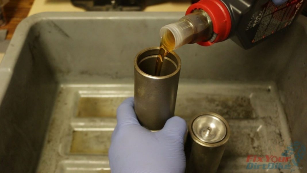
- Step 17: Fill the reservoir halfway and make sure oil is flowing into the body.
- *You will not see oil flow right away. Keep in mind that the compression damper is designed for forced oil flow, so let the shock sit for a few minutes. If no oil is flowing, you may have a damaged damper.
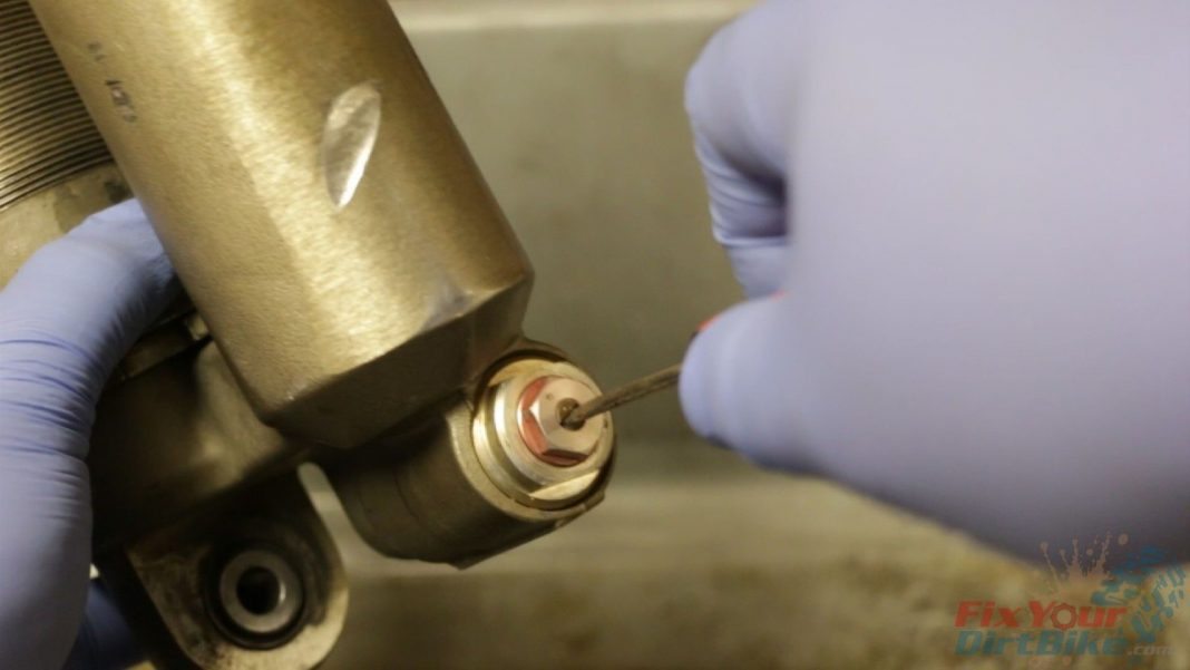
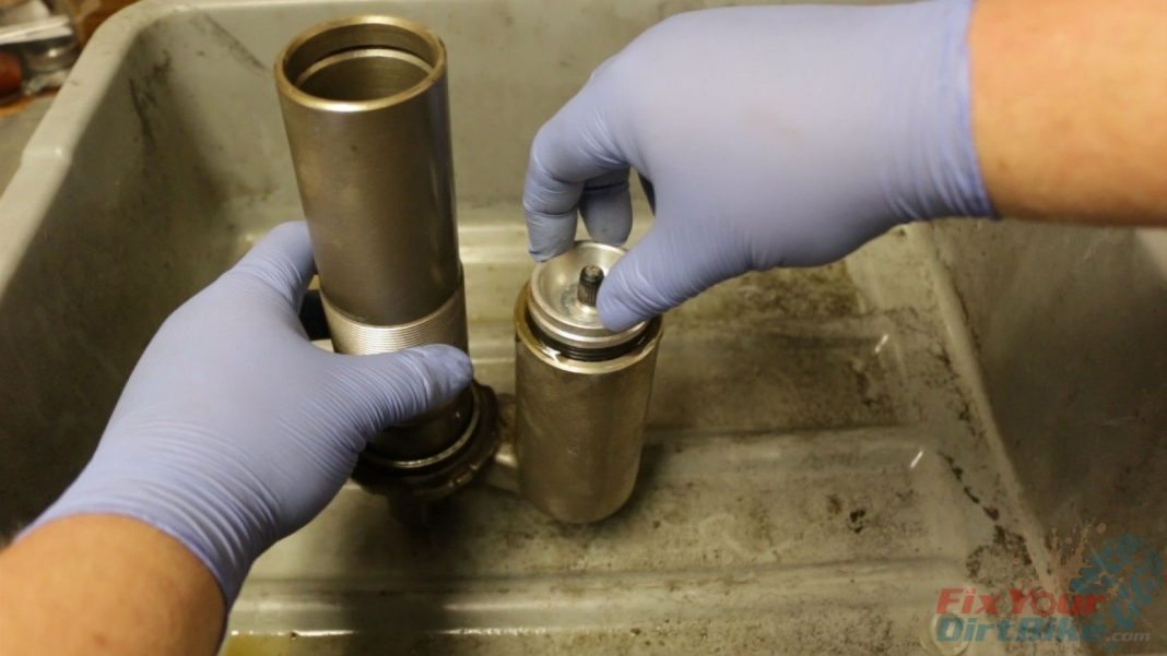
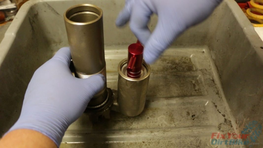
- Step 18: Install the valve cap and install the reservoir cap and bladder. You want to see the reservoir overflow, as this forces air from the reservoir.
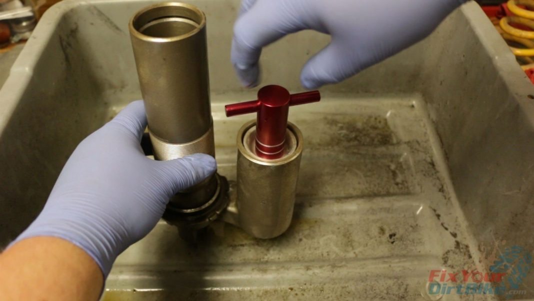
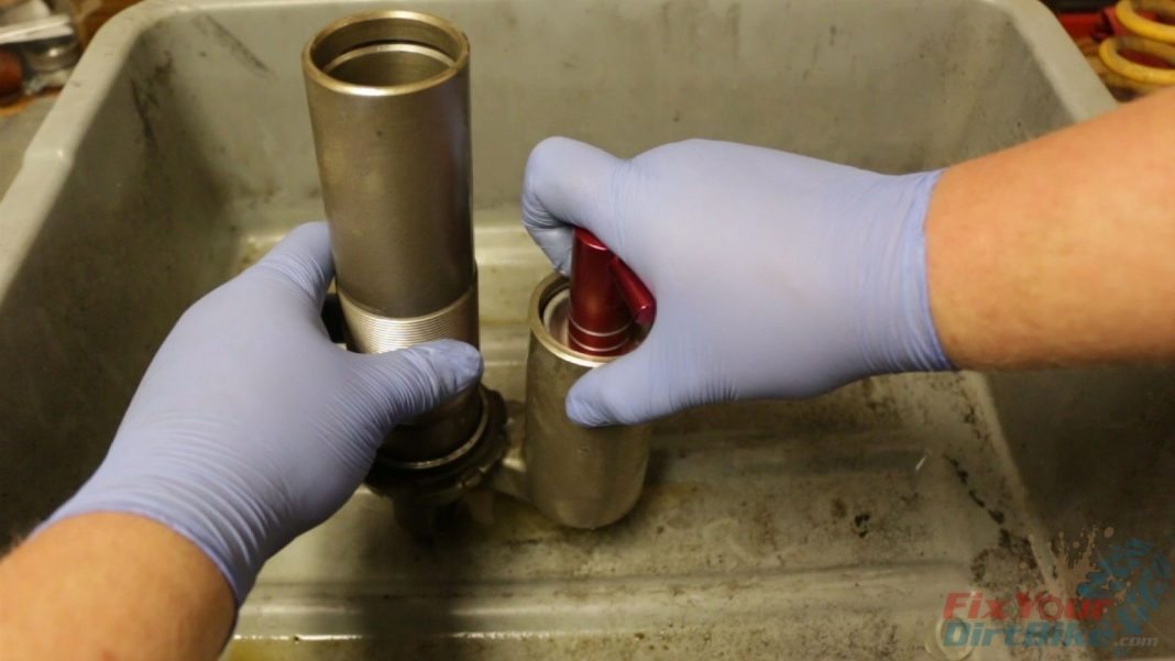
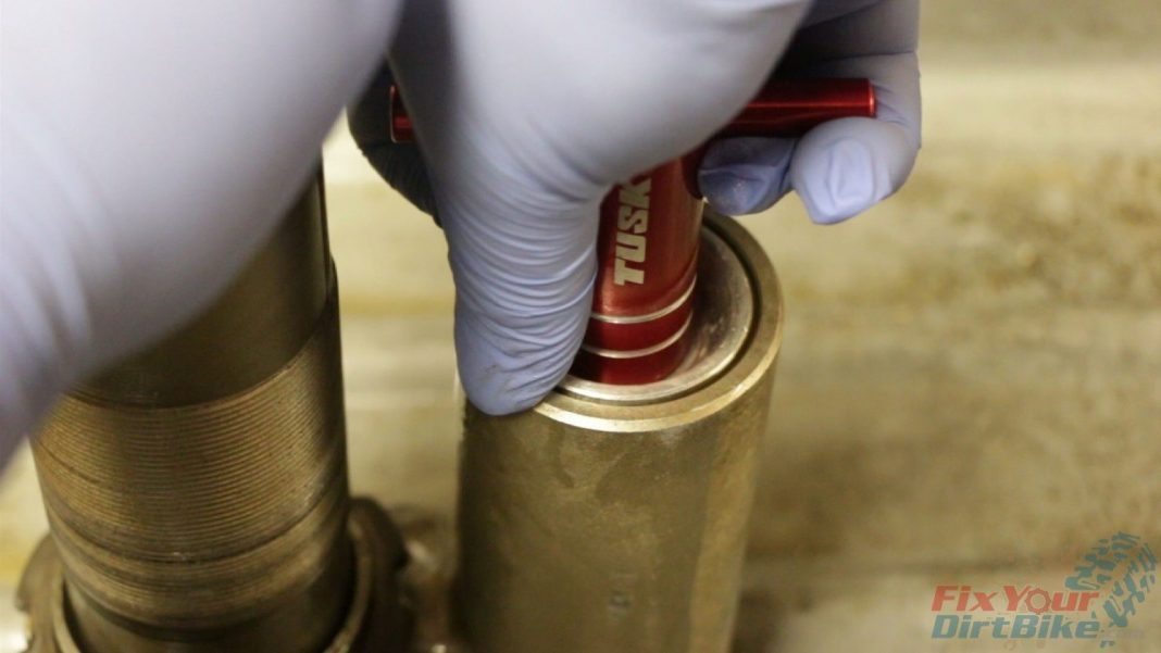
- Remove the valve cap and install the reservoir cap tool. Force the reservoir cap down far enough to expose the circlip groove.
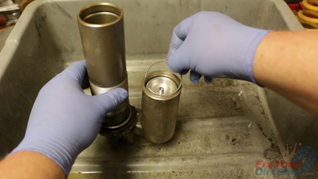
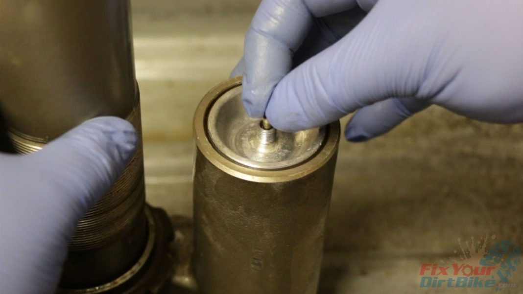
- Install the circlip, reinstall the reservoir cap tool, and pull the cap up to the circlip.
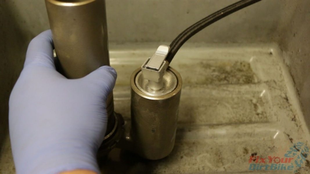
- Remove the reservoir tool and install the valve stem.
- Using a low-pressure pump, fill the bladder to around 40 to 60 PSI. This will seat the reservoir cap to the circlip, as well as force oil into the shock body.
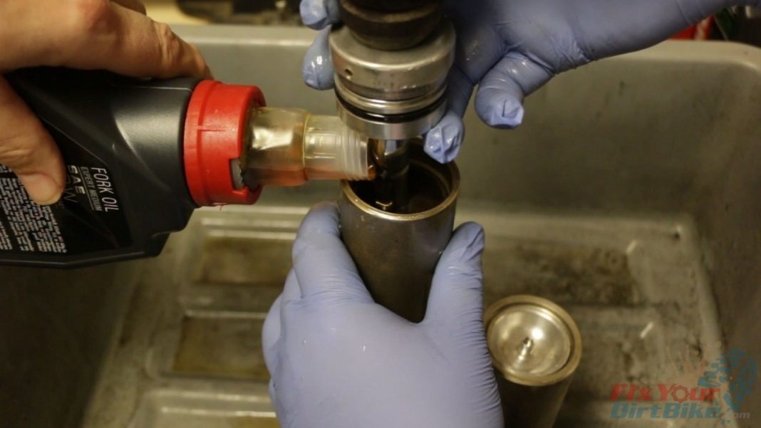
- Step 19: Fill the shock body halfway with oil.
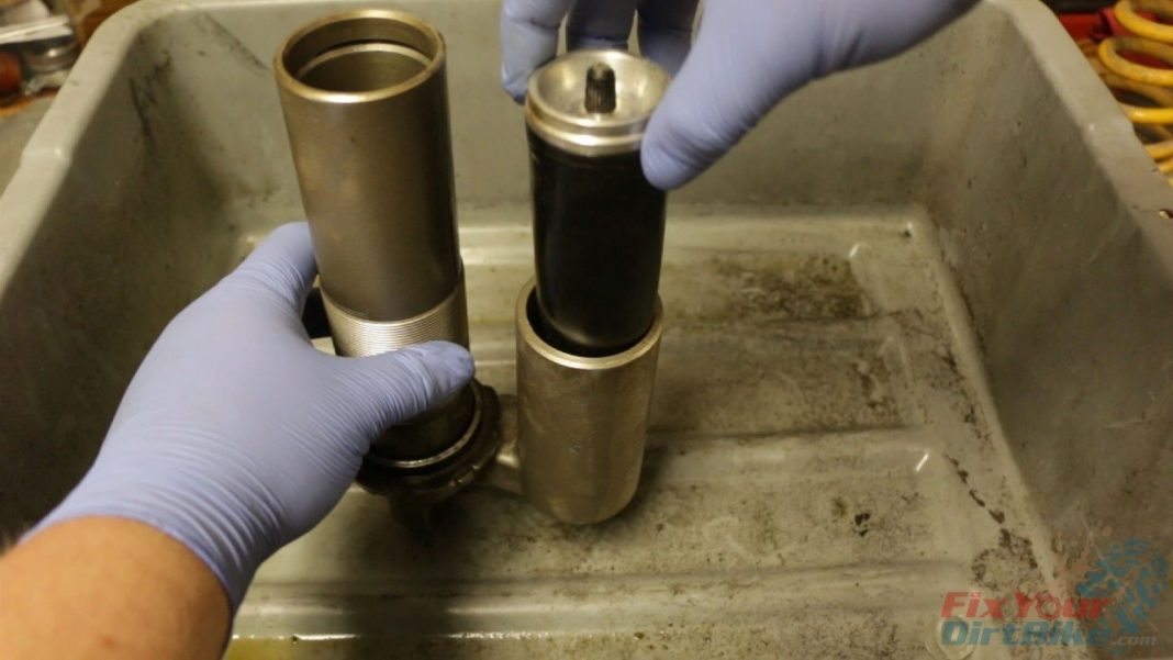
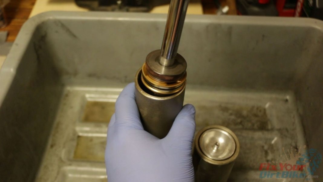
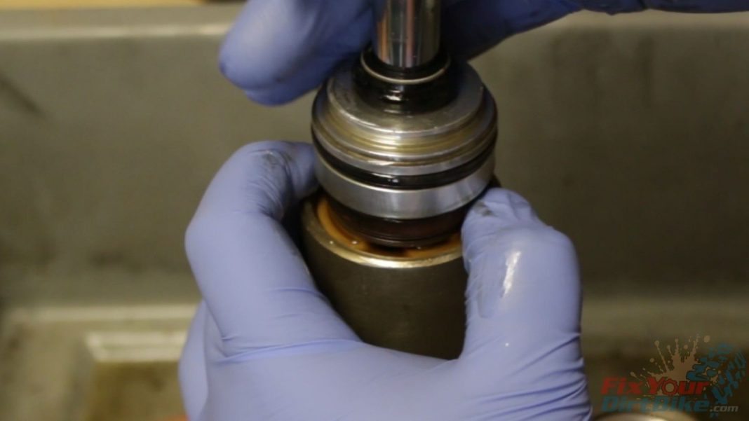
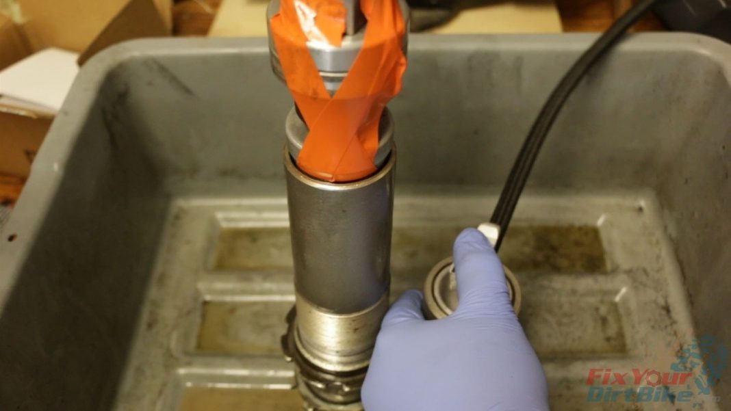
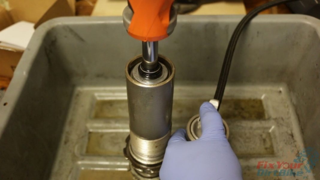
- Step 20: Install the shock shaft, working it up and down to remove any trapped air. As you go, continue filling the shock body with oil.
- DO NOT ATTEMPT TO SEAT THE SEAL HEAD!
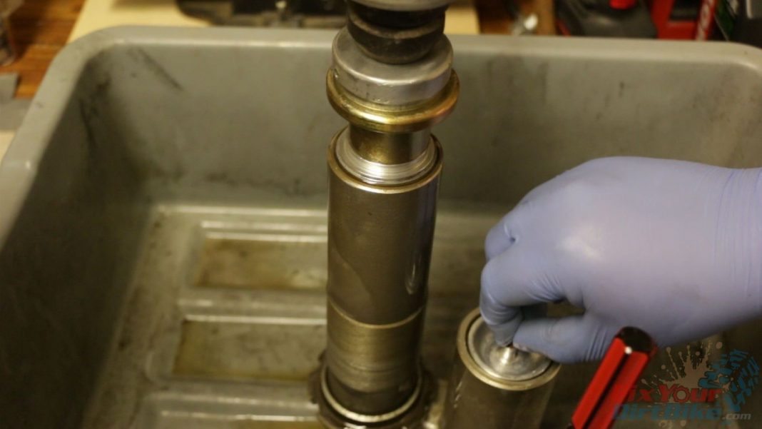
- Step 21: Release the pressure from the reservoir bladder and remove the valve stem. This will allow the bladder to compress, making room for the seal head.
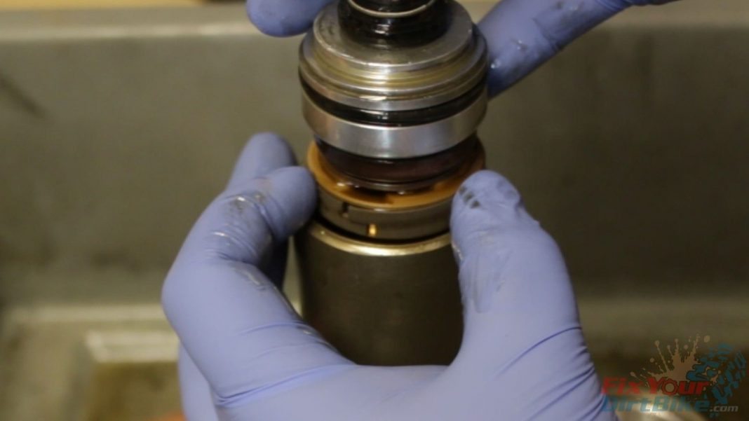
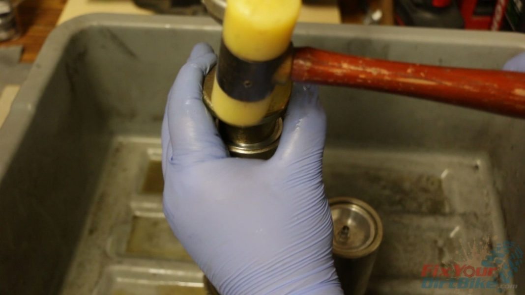
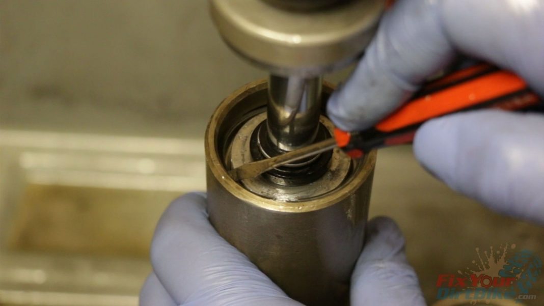
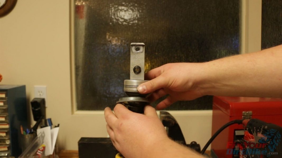
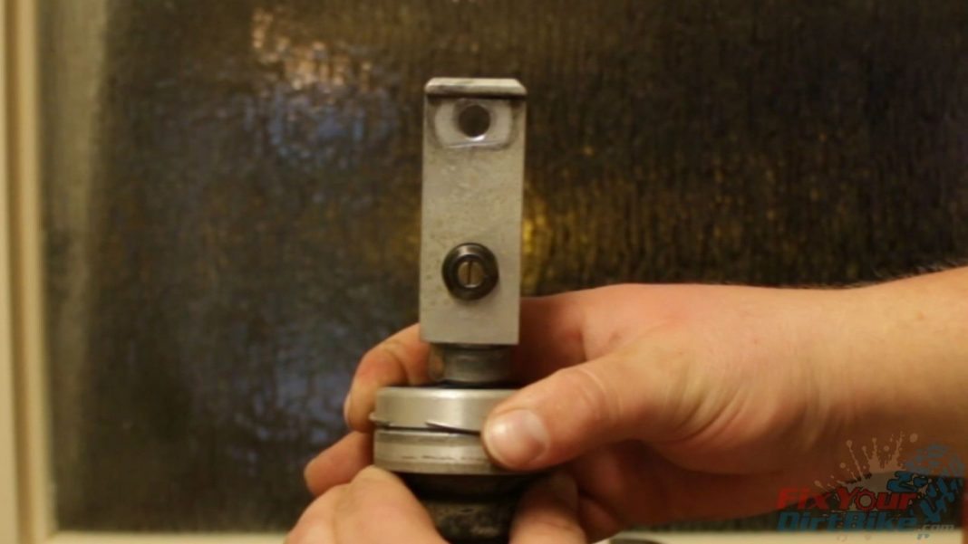
- Step 22: Using your seal head setting tool, pound the seal head into the shaft body just enough for the circlip groove to be exposed.
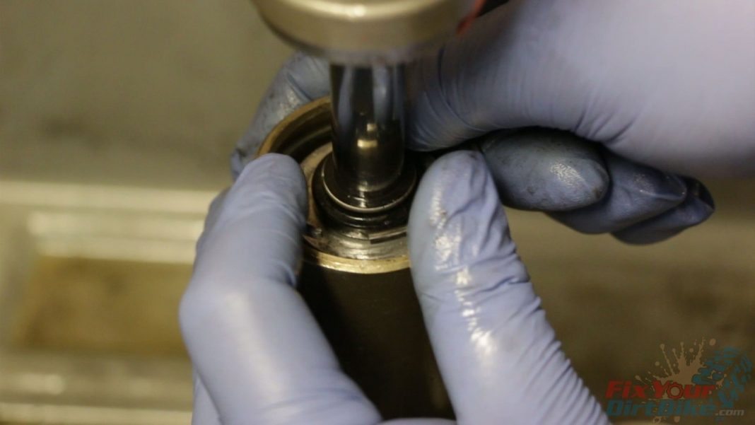
- Install the circlip and valve stem.
- Step 23: Inflate the bladder to 40 to 60 PSI to seat the seal head against the circlip.
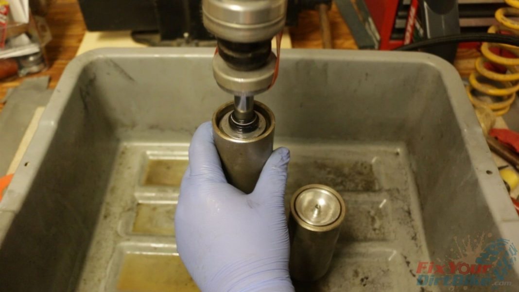
- Step 24: Pump the shock shaft and check for any obvious leaks at the seal head and reservoir.
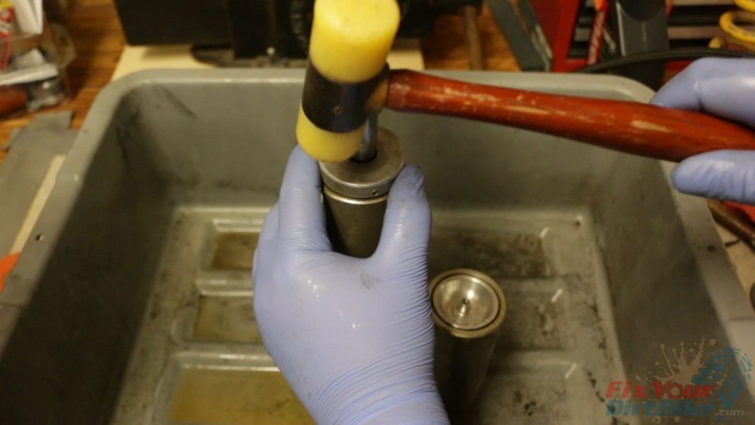
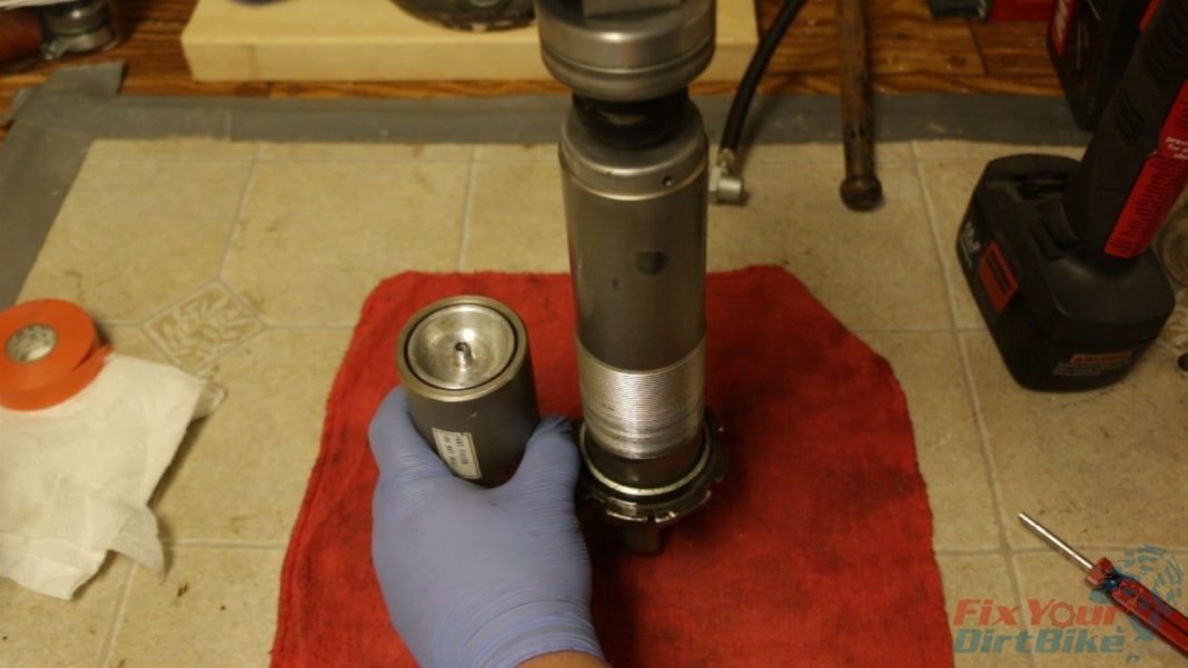
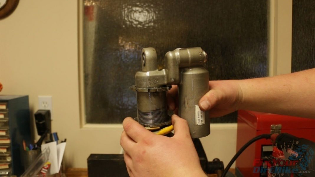
- Step 25: Install the shock body cap. Hammer lightly around the edge of the cap, so it seats evenly.
- *The punch holes in the cap also act as weep holes so you can check for slow leaks in the future.
- Let the shock sit for a while, then come back and test the action again while checking for leaks.
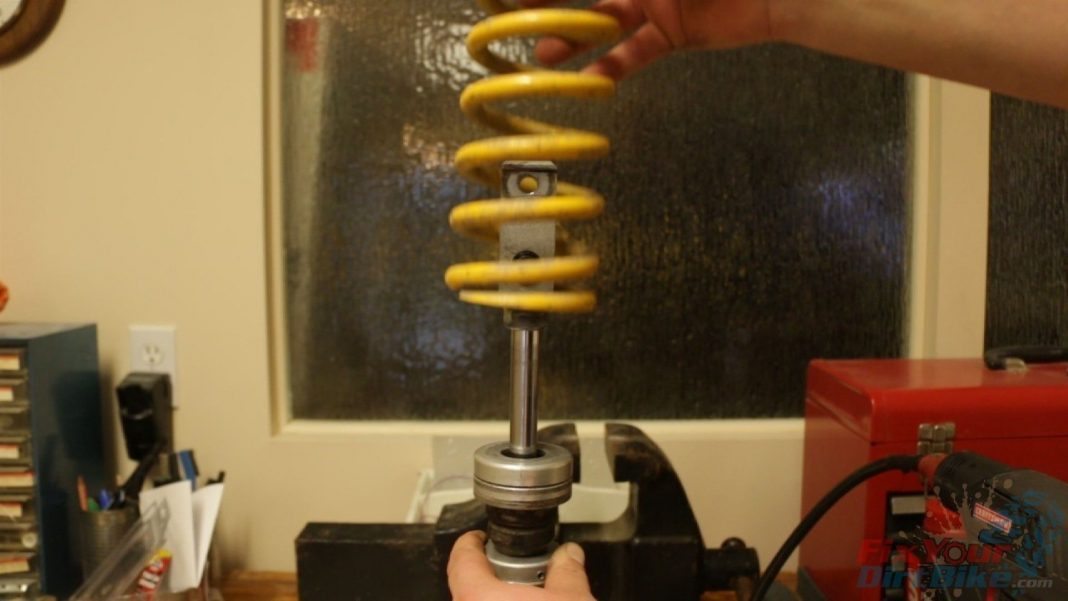
- Step 26: Install the spring, plate, and circlip. Tighten the preload adjustment nut, and fill with 130 – 150 PSI of NITROGEN!
- *You will need to go to a shop for the nitrogen.
If you have any questions or anything to add, please leave them in the comments or on our FaceBook page!
Back To 1997-2001 Honda CR250 Master Repair Index